


Vertical Laminar Airflow BLVR-303
- Sea, Air, Door to Door Shipping
- 1 Year Warranty
- US & European Standards
Compact design required for operations in an ultra clean, dust free environment. Ideal for laboratory applications where product protection is required. Small size saves precious laboratory space. Contains ultra thin filter including static pressure box without separator. Larger space permits working with laboratory equipments within the workspace.
- ETL certified, Satisfy North American market.
- With memory function in case of power-failure.
- Audio and visual alarm(Abnormal airflow velocity).
- Interlock function: UV Lamp and blower LED Lamp.
Specification
Features
Applications
| Type | The ETL certified vertical laminar flow cabinet |
| Airflow Velocity | Average of 80~99 fpm |
| HEPA Filter | One,99.995% efficiency at 0.3μm |
| Pre-Filter | Polyester fiber |
| Work Surface Height | 750~1010mm |
| Max Opening | 480mm |
| Working area Material | 304 stainless steel |
| Main Body Material | 1.2mm Cold-rolled steel with anti-bacteria powder coating. |
| Front Window Material | Motorized, 5mm toughened glass, anti-UV |
| Waterproof Sockets | One socket (Double type), America standard, Max.Power: 500W |
| UV Lamp | 18W x1 |
| LED Lamp | 10W x1 |
| Display | LCD Display |
| Illumination | ≥300lx |
| Noise | ≤68dB(A) |
| Standard Accessory | Manually height adjustable base stand; LED lamp; UV lamp; Wind speed sensor; Waterproof socket. |
| Internal Size | 700Wx575Dx625H mm |
| External Size | 800x700x(2090~2340)mm |
| Package Size | 940Wx970Dx1560H mm |
| Gross Weight | 190kg |
| Consumption | 750W |
| Power Supply | 110V±10%V, 60HZ |
- ETL certified, Satisfy North American market.
- With memory function in case of power-failure.
- Audio and visual alarm(Abnormal airflow velocity).
- Interlock function: UV Lamp and blower LED Lamp.
Pharmaceutical, Pathology lab, Life science research, Plant tissue and cell culture
Operating Manual for BLVR-303
1. Unpacking, Installation and Debugging
1.1 Unpacking
1.2 Accessories Checking
1.3 Installation Conditions and Operating Environment
1.4 Installation
1.5 Checking after Installation
2. User Instructions
2.1 Functions
2.2 Product Structure
2.3 Instructions for Operation
2.4 Daily Maintenance
2.5 Replacement Parts List
2.6 Wiring Diagram
3. Trouble Shooting and Solutions
3.1 Common Failures and Solutions
3.2 Replacement of Fuse
3.3 Replacement of LED Lamp
3.4 Replacement of UV Lamp
3.5 Label Description
4. Warranty
1. Unpacking, Installation and Debugging
Please firstly check if the packing box is in good condition. If the packing box is damaged, please take photos.1.1 Unpacking
Choose the proper unpacking method and tools as shown in the below pictureFor wooden box:
1) Method 1 Necessary tools for unpacking: Electric drill with hexagon dead M8
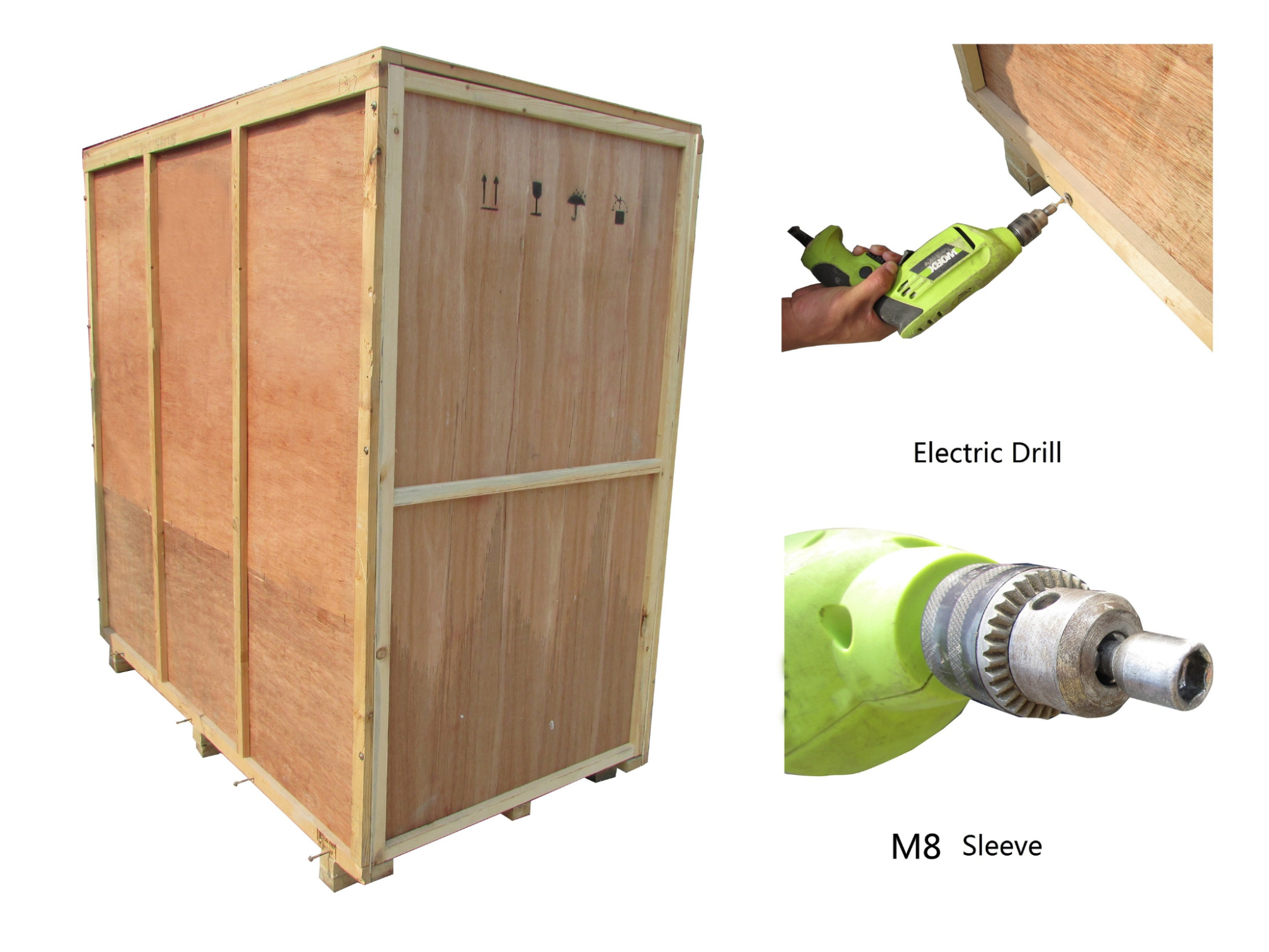
Figure 1
2) Method 2 Use M8 Wrench to unpack
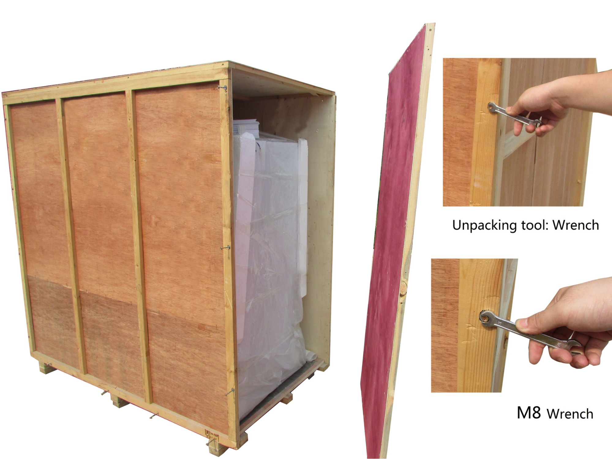
Figure 2
The following diagram demonstrates quick unpacking procedures. Remove the screws as shown in the below diagram, then remove the wooden sheet to right and wooden box to left.
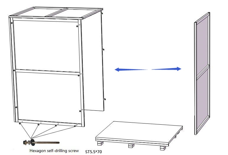
Figure 3
1.2 Accessories Checking
Refer to the packing list and check the accessories.The spare parts as back up, it can be normally used after unpacking.
Packing list (BLVR-303)
| Items | Quantity | Position |
| Main body | 1 unit | Wooden box |
| Base stand | 1 set | Connected with cabinet body |
| Power cord | 1 pc | Packaging Bag(On top of main body) |
| Fuse (5A) | 1 pc | Packaging Bag(On top of main body) |
| UV Lamp(T6 20W) | 1 pc | Paper Packing(On top of main body) |
| User manual | 1 pc | File Packet(On top of main body) |
| Inspection report | 1 pc | File Packet(On top of main body) |
| Certification of quality | 1 pc | File Packet(On top of main body) |
| Warranty Card | 1 pc | File Packet(On top of main body) |
Table 1
1.3 Installation Conditions and Operating Environment
Laminar Flow Cabinet shall be placed in the protective area of an air stream, and the working area of the Laminar Flow Cabinet cannot be right opposite to the door or window, and should be away from the air outlet of air conditioner to prevent the air flow from the ventilation system, air conditioning, door, window and personnel movement may cause airflow impact on the LAF.At least 300mm gap must be kept in each side of the Laminar Air Flow for inspection.
Working environment:
(1) Only applicable for indoor operation
(2) Ambient temperature: 15° C~35° C
(3) Relative Humidity: ≤75%;
(4) Atmospheric pressure range: 70 kPa~106 kPa;
(5) Electrical parameters: Adequate power supply to the laminar flow cabinet (See 2.1.4 Technical Parameters);
(6) Power supply need to be grounded; (Judging method: Test the live wire and the neutral wire of the socket with multimeter. The voltage between live and ground should equal to the voltage of local electrical grid, and the voltage between neutral and ground should equal to 0. Otherwise the power supply is not grounded correctly).
1.4 Installation
(Figure 4)a. Remove all the packing materials;
b. Check for Physical damage or scratch the surface of main body during transit. Make sure there is no damage, scratch, deformation on main body;
c. Confirm the complement of accessories according to the list;
d. The height of leveling feet can be adjusted. Counterclockwise the leveling feet, cabinet (or base stand)can be moved when the height of leveling feet is less than the height of caster; clockwise the leveling feet, cabinet (or base stand)can be moved when the height of leveling feet is larger than the height of caster;
e. The whole LAF Instrument must be moved to the final working place where it can be Installed.
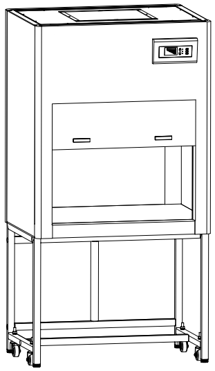
Figure 4
1.5 Checking after Installation
First, check the electrical power supply, make sure the voltage and frequency match with the Instrument power supply rating, then check the follows items after power on:| Checking Items | Normal working status |
| Fan | Runs normally |
| LED Lamp | Lamp lights up after pressing button |
| UV Lamp | Lamp lights up after pressing button |
| Screen Buttons | All buttons work effectively |
Table 2
 If you have any questions, please contact Biolab or our agent to debug. Debugging method in the After-sale service manual.
2. User Instructions
2.1 Functions
2.1.1 Product Concept
Laminar Flow Cabinet – LAF Cabinet is only for sample protection.Laminar Flow Cabinet is a work bench or similar enclosure, which creates a particles-free working environment by taking air though a filtration system and exhausting it across a work surface in a laminar or unidirectional air stream. The laminar flow cabinet is enclosed on the sides and kept under constant positive pressure in order to prevent the infiltration of contaminated room air. BLVR-303 is vertical type Laminar Flow Cabinet.
2.1.2 Working theory/Air flow Pattern and Protected Area Figure
(Figure 5)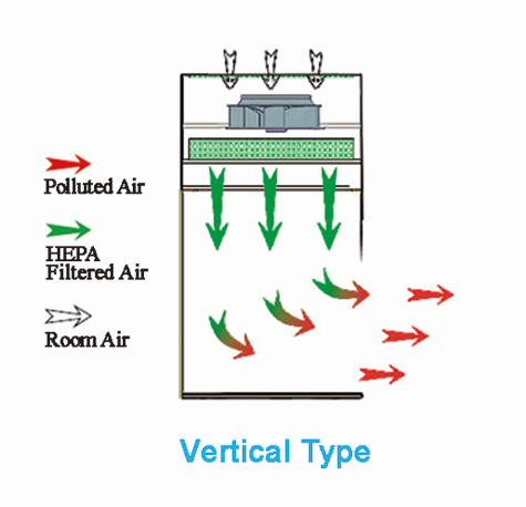
Figure 5
2.1.3 Protected Objects
Laminar flow cabinets are designed to protect samples and create partial particles-free environment. The main function is to make sure the accuracy of experiment at the operating area. However, it could not protect the environment or operators.2.1.4 Technical Parameters
| Model Parameters | BLVR-303 |
| External Size (W*D*H) | 802*650*1550 mm |
| Internal Size (W*D*H) | 800*530*540 mm |
| Power Supply AC | 220V±10% 110V±10% |
| Frequency | 5 0Hz 60Hz |
| Consumption | ≤350 W |
| Airflow Velocity | 0.3~0.5m/s |
| UV Lamp Consumption | 20W |
| LED Lamp Consumption | 8W (LED) |
| HEPA Filter Efficiency | 99.999% efficiency at 0.3um |
| Noise | <65dB |
Table 3
Note: the company reserves all the rights to changes in product design , if there are any design change, we will not inform in advance.
Vibration Amplitude:
The net vibration amplitude between frequency 10Hz and 10KHz should not exceed 5μm(rms).
1) Illumination
The average illumination is equal or more than 350 lux,
2) Electrical properties
The voltage increases to 1390V (AC) in 5s and keep for another 5s without breakdown.
Grounding resistance ≤0.1Ω.
2.2 Product Structure
2.2.1 Structural Composition of BLVR-303
(Figure 6)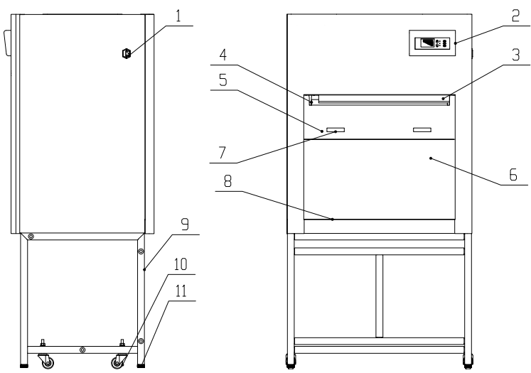
Figure 6
1. Socket
2. Control panel
3. LED light
4. UV lamp
5. Front window
6. Rear window
7. Handle
8. Work table
9. Base stand
10. Caster
11. Leveling feet
2.2.2 Structure Composition
1) Driving system of front windowDriving system consists of constant spring and front window.
2) Air filtration system
Air filtration system is the core system of laminar flow cabinet. It consists of blower and HEPA filter system. The main function of air filtration system is to transfer filtered air to work area, ensure the airflow velocity, and keep cleanness of work area.
3) UV lamp
The UV lamp located at the top of the work zone effectively disinfects the entire work zone by emitting a wavelength of 253.7nm
4) LED light
The laminar flow cabinet is equipped with LED light, which ensures the standard requirement of average illumination is met.
5) Control panel (Figure 7)
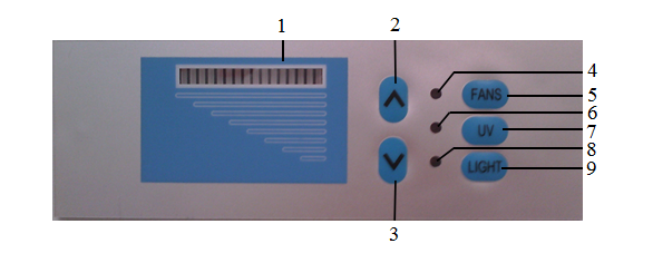
Figure 7
1.Gears Indicator
2.Increase Air Velocity
3.Decrease Air Velocity
4.Fans Indicator
5.Fans
6.UV Indicator
7.UV
8.Light Indicator
9.LED Lamp
a. Gear indicator
To see air speed gears of the equipment through gears indicator.
b. Soft touch buttons
Laminar flow cabinet’s main functions are executed by touch-buttons.
“Light” is lighting button, which control the working state of the LED light. Each press results state of lighting lamp once and brightness level of lighting lamp exchange between bright and dark on the control panel. That is “LIGHT” change from appear to disappear or from disappear to appear. (This key is invalid when sterilization key is open)
“UV” is ultraviolet button, which control the working state of the ultraviolet lamp. Every press will result state of UV lamp once and brightness level of UV lamp exchange between bright and dark. That is “UV” change from appear to disappear or from disappear to appear. (This key is invalid when the Lighting key and Fans key is open)
“FANS” is blower control button, which control the working state of blower. Every press will exchange the working state once and brightness level of Fans exchange between bright and dark. (This key is invalid when the Ultraviolet key is open)
The blower airflow increase button(”∧” “∨”): When the blower is operating, press button “∧” to increase the wind speed: press button “∨” to decrease the wind speed.
6) Fuse
The cabinet is equipped with main power fuse. Fuse label is corresponding to the relevant specifications, please refer to 3.5.1 Fuse Label. And refer to 3.2 Replacement of Fuse when replace it.
7) Structure
a) Cabinet body is made up of 1.2mm cold-rolled steel with anti-bacteria powder coating. The structural strength and stability are enhanced.
b) Work table is made up of 304 stainless steel which provides corrosion resistance as well as attractive appearance.
c) Base stand is made up of cold-rolled steel with anti-bacteria powder coating.
d) Control panel with soft touch buttons is user-friendly and multifunctional.
2.3 Instructions for Operation
2.3.1 Normal Operation Notice
1) Make sure input voltage is correct and stable. The rated load of main power socket should be higher than laminar flow cabinet consumption. Plug must be well grounded;2) Moving principles of different samples inside cabinet: When two or more samples need to be moved in, be sure that low-polluting samples should be moved first then high-polluting samples. Movement of items should also follow the principles of moving slowly and steadily.
3) The weight of items placed in the cabinet should not be more than 23Kg/25×25cm2;
4) Avoid vibration: avoid using vibration equipment (eg centrifuges, vortex oscillator, etc.) inside the cabinet. Vibration would cause lower cleanliness of operating area and affect operator protection.
5) NO FLAME: No flame is allowed inside the Laminar flow cabinet. Using of fire will lead to airflow disorder, and filter damage. If sterilization is required during the experiment, infrared sterilizer is highly recommended.
6) HEPA filter life: With the usage time increasing, dust and bacteria accumulate inside HEPA filter. Filter Resistance is getting bigger, when it reaches the maximum point, the speed requirements can’t be met. Then need contact Biolab service department to get a new one. The used filter should be processed as medical waste.
7) The fan and its underside is mute bellows, which is sealed strictly in the factory. The operator is not allowed to remove or loose screws of those parts. If necessary, please contact service personal or agent.
8) The maximum storage period is one year. If the period is more than one year, performance test should be done.
Serious declaration:
NOTE: Biolab WILL NOT BE RESPONSIBLE FOR ANY RISK OR DAMAGE ARISING FAILURE DURING USAGE BY UNTRAINED OPERATOR AND MISHANDLING THE LAF. THE OPERATOR OF THE LAMINAR FLOW CABINET SHOULD BE TRAINED ENOUGH BEFORE USING THE LAF.
2.3.2 Operation Process
a) Connect to a suitable power supplyb) Press relevant buttons and check if work normally(functions and operations, pls kindly refer to the instruction of 2.2.2); Checking the fan, UV lamp and LED lamp if work normally, the air velocity if meet standard requirements.
c) The cabinet should be sterilized by UV lamp for at least 30 minutes with the window fully closed before any experiment.
 NOTE:
NOTE:1) For safety of eyes and skin, people should leave the room during UV sterilization.
2) UV lamp should be checked regularly. It should be replaced when either the total working time reaches 600 hours or the intensity is lower than the requirement.
d) Please move up the front window to proper height above the work table and turn on the blower. Make sure the experiment should be started after fan working for at least 30 minutes.
For operating safety, please put testing materials inside the cabinet in advance.After finishing the experiment, please fully close the front window and make sure to sterilize the cabinet by UV lamp for at least 30 minutes before turning off the cabinet.
2.4 Daily Maintenance
A detailed daily record of operating time is recommended, as the accumulated using time will directly affect the plan of maintenance. To avoid electric shock, please cut off ALL power before applying maintenance for the cabinet!Preparation before Maintenance: Please remove all the items which are inside the cabinet
Material needed: soap, hot water or warm water, a piece of soft cotton cloth, a piece of dry cloth or towel, medicinal alcohol or other disinfectants.
2.4.1 Clean the Surface of Working Zone
Wipe the entire surface with a soft cotton cloth which has been soaked with concentrated liquid soap. Afterwards, wipe off the foam with another cotton cloth or towel which has been soaked with clean hot/warm water. At the end, wipe the entire surface with a dry cotton cloth or towel rapidly.For the contaminated or dirty work surface and sump, use medicinal alcohol or other disinfectant to wipe.
Disinfectants used for wiping should not damage the 304 stainless steel.2.4.2 Clean the External Surface and Front Window
Use a piece of soft cotton cloth or towel with non-abrasive household cleanser to wipe the surface.2.4.3 Overall Maintenance Period
The recommended interval period for comprehensive maintenance is either one year or 1000 working hours.2.4.4 Maintenance Methods
1) Weekly or daily maintenancea. Disinfect and clean the operating area(Please refer to 2.4.1 Clean the Surface of Working Zone);
b. Clean the external surface and front window(Please refer to 2.4.2 Clean the External Surface and Front Window);
c. Check the various functions of the cabinet if abnormal;
d. Record down the maintenance result;
2) Monthly maintenance
a. Clean the external surface and front window(Please refer to 2.4.2 Clean the External Surface and Front Window);
b. Use towel with 70% medicinal alcohol or 1:100 dilution of household bleach to wipe the working table, the inner face of front window and the inner wall surface of the working area(exclude the top wind grid). Use another towel with sterile water to wipe those area to erase the remain of chlorine.
c. Check the various functions of the cabinet if abnormal;
d. Record down the maintenance result;
3) Annual maintenance
a. Check the front window tubular motor, make sure both of them are well connected to the motor with same tightness.
b. Check the UV lamp and LED light.
c. Apply for overall performance test of the cabinet annually to ensure that the safety meets requirements. User is responsible for testing costs.
d. Record down the maintenance result.
Cut off the power during maintenance2.4.5 Storage Conditions
Laminar flow cabinet should be stored in a warehouse with relative humidity no more than 75%, and temperature lower than 40℃. The warehouse with should have good ventilation performance, without acid, alkali and or other corrosive gas. Storage period shall not exceed one year. Laminar flow cabinet stored for more than one year needs to be unpacked and checked before selling and using. Only the tested and qualified cabinet could be sold.2.5 Replacement Parts List
BLVR-303 replacement parts list| Number | Name | Specification |
| BH-01 | Fuse | 5A |
| BH-02 | Lamp holder T8 | LG13-01A |
| BH-03 | UV lamp | T6 20W |
| BH-04 | LED T5 stand | T5 8W |
| BH-05 | UV lamp ballast | 1*TL8-18W |
| BH-06 | HEPA filter | 720*430*50 |
| BH-07 | Fan | FS133C |
| BH-08 | Control panel | Laminar flow cabinet control panel(Ten light pillar) |
| BH-9 | Tempered glass | Size 748*580*5 |
| BH-10 | Common glass | Size 714*570*5 |
| BH-11 | Constant spring component | Constant spring,Nylon sleeve,Nylon set of baffle |
Table 4
2.6 Wiring Diagram
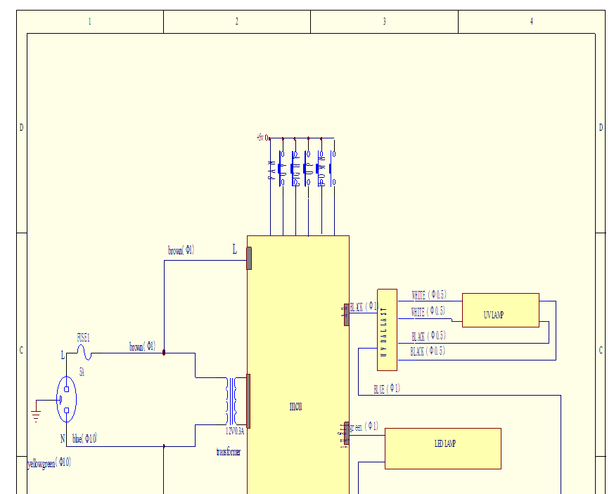
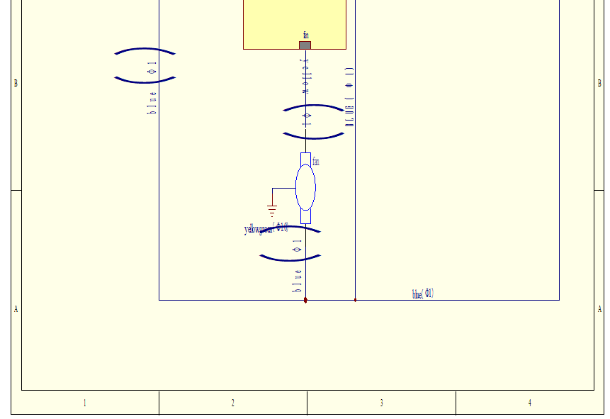
Figure 8
3. Trouble Shooting and Solutions
3.1 Common Failures and Solutions
Please confirm that the power is well connected, the power cord and fuse are in good condition(without any damage).| Failure | Checking parts | Measures |
| LED lamp fail to work | LED stand plug | Connect the plug and stand tightly |
| LED stand | Replace stand | |
| Circuit | Check the circuit | |
| Control panel | Replace the control panel | |
| UV lamp fail to work | Interlock | Check the blower and LED lamp turn off or not |
| Lamp holder | Connect the tube and lamp holder tightly | |
| Lamp tube | Replace the lamp tube | |
| Ballast | Replace the ballast | |
| Circuit | Check the circuit | |
| Control panel | Replace the control panel | |
| Button fail to work | Control panel | Make sure the power is well connected and the fuse is in good condition |
| Check if the button is broken | ||
| Make sure the connecting wire is well connected | ||
| Replace the control panel | ||
| Blower fail to work | Blower | Replace the blower if it is damaged |
| Circuit | Check the circuit | |
| Control panel | Replace the control panel | |
| No electricity in equipment | Power supply | Check whether the power supply is well connected |
| Power cord | Check whether power cord is in good condition | |
| Fuse | Check whether the fuse is damaged | |
| Potential transformer | Check whether the transformer works normally | |
| Control panel | Replace the control panel | |
| Display fail to work | Connection wires | Check connection wires if in good connection |
| Display screen | Check whether the screen is in good condition | |
| Control panel | Replace the control panel |
Table 5
NOTE:1) The above trouble shooting methods should be done by qualified electricians under safe conditions(cut off power supply). Other components should not be removed. Risk caused by failing to follow those instructions would be responsible by user.;
2) Please contact Biolab or our agent if a failure could not be traced or solved. Do NOT repair the equipment without a qualified electrician;
3) The trouble shooting and repair of this equipment only could be undertaken by trained and recognized technicians;
Please contact Biolab or our agent to order required component or part. The model number and the serial number of purchased cabinet need to be indicated.
3.2 Replacement of Fuse
Replace the fuse using a flat-blade screwdriver socket pulled out of the fuse holder and replace, then press it back.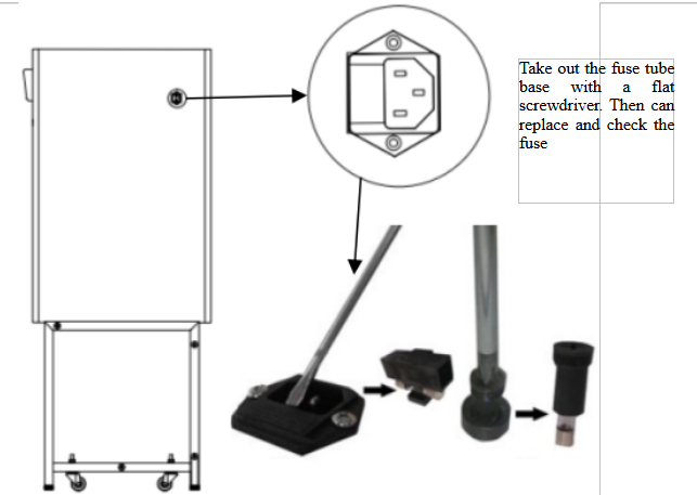
Figure 9
3.3 Replacement of LED Lamp
When the LED light needs to be changed, turn off the power. Then remove the LED stand, unplug the right side, After replacing a new LED stand, inserted into the inclined slot.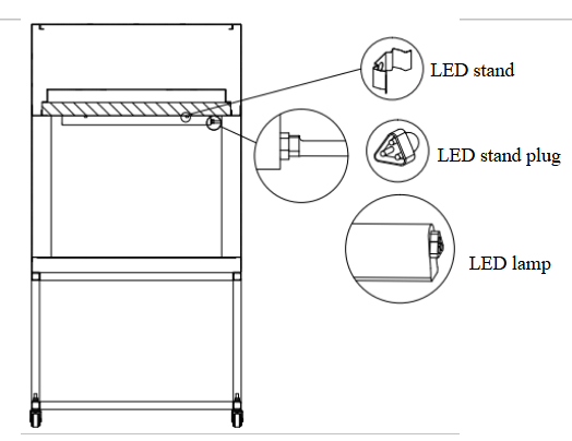
Figure 10
3.4 Replacement of UV Lamp
Ultraviolet intensity should be tested regularly in order to achieve a good disinfection effect. We recommend use Ultraviolet intensity test card to confirm if we need to replace UV lamp. when using UV lamps reach to the time of 600 hours, we recommend to replace the lamp. When replacing, turn off the power, and then screw the lamp tube 90 ° and take it off, then replace the correspondence type of lamp, and put it to the lamp holder and and screw 90 ° in reverse direction.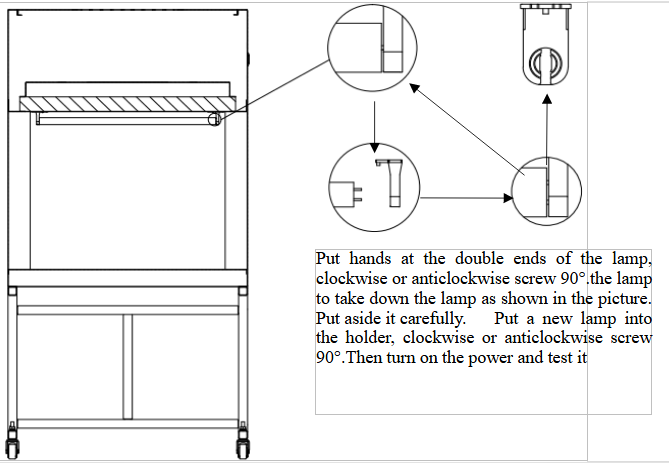
Figure 11
3.5 Label Description
3.5.1 Fuse Label
Note: 5 A fuse label
4. Warranty
4.1 Warranty is 12 months from EX-factory date (excluding consumable accessories, UV and LED lamp, fuse).4.2 Biolab would not be liable for any repair of damage caused by improper operation..
4.3 If the warranty has been expired, Biolab would still responsible for repair with relative charges.
4.4 Life time of laminar flow cabinet is 8 years from production date on the label.
4.5 Biolab would provide equipment drawings and necessary technical data for maintenance companies or personnel trained by Biolab engineers.
Warranty declaration: One-year Warranty, Life-long Maintenance