


Vacuum Oven BOVA-5801
- Sea, Air, Door to Door Shipping
- 1 Year Warranty
- US & European Standards
- With reservation and timing functions, there is no need to wait, which effectively improves the efficiency of the experiment
- Available in Chinese and English menus to meet different language needs, with °C / °F conversion
- The machine above 90L has moving casters for flexible and convenient movement
- The door is closed and elastically adjustable, and the integrated molded silicone rubber door seal ring ensures the vacuum inside the box
Specification
Features
| Capacity | 24 L |
| Temperature Range | RT+10°C - 200°C |
| Temperature Accuracy | ±1°C |
| Display Resolution | 0.1°C |
| Max degree of vacuum | 99 Pa |
| Standard Max number of shelves | 2 (3) |
| Max load per shelf | 20 Kg |
| Interior Material | 304 stainless steel |
| Internal Dimension | 300Wx300Dx275H mm |
| Exterior Dimension | 445Wx505Dx590 |
| NW | 60 Kg |
| Inert gas air inlet | Standard |
| Electrical Requirement | AC 220 V / 50 Hz |
| Power Consumption | 700 W |
- With reservation and timing functions, there is no need to wait, which effectively improves the efficiency of the experiment
- Available in Chinese and English menus to meet different language needs, with °C / °F conversion
- The machine above 90L has moving casters for flexible and convenient movement
- The door is closed and elastically adjustable, and the integrated molded silicone rubber door seal ring ensures the vacuum inside the box
- Protection on instruments: Comply international standard secondary temp limiting alarm system, when the heating is out of control or exceeds the maximum limit temperature, the heating is automatically cut off with sound and light alarm, ensure operating is safe without any accident
- Protection on key components: Key components are equipped with over-current, over-temperature, overload and other safety protection to prevent accident
- Protection on samples: When the temperature inside the box is higher or lower than the set temperature, the alarm will start to cut off the heater, with sound and light alarm to remind the operator to protect the sample from normal test without accident
- Protection on operato: The cabinet and door are specially insulated to make the surface temperature of the cabinet low, ensuring the operator's safety and no accidents
- Breakdown message provided: When the instrument breakdown, the message will shown on the screen to help operator clearly check
- The touch screen type standard with a USB interface, which can record the change status of the temperature parameters
- The LCD screen is option for USB interface
- It can be equipped with RS232 data interface, which can realize remote control of the machine through software
- RS-232 and USB can be selected one of them
Operating Manual for BOVA-5801
1. Warranty
2. Contents of package
3. Installation requirements and safety tips
3.1 Installation requirements
3.2 Instruction for Safety
4. Product introduction
4.1 Function introduction
4.2 Specifications
4.3 Summary of structure and function
5. Temperature and timing setting
5.1 Function introduction
5.2 Program mode operation screen
5.3 Operation mode selection
5.4 Program content editing
5.5 Fixed value mode operation
5.6. Schedule boot settings
5.7. Operation precautions
6. Maintenance and attention
7. Troubleshooting
1. Warranty
Thank you for purchasing a “being” instrument. In normal use conditions, the instrument is guaranteed for a period of 24 months from the date of purchase.The warranty is valid only if the product is original. It does not apply to any product or parts of it that have been damaged due to incorrect installation, improper connections, improper use, accident or abnormal conditions of operation.
The manufacturer declines all responsibility for damage caused by failure to follow instructions, lack of maintenance and any unauthorized modification.
2. Contents of package
The instrument is delivered complete with the following parts:• Vacuum Oven (main unit).
• 2 aluminum plate shelves(3 aluminum plate shelves with BOVA-5803)
• Power supply cable
• 2 core of fuse
• Connecting vacuumizing pipes (interior diameter:Φ14mm thickness of the wall:8 mm)
• Wrench
• Vacuum pump(optional)
• User manual
3. Installation requirements and safety tips
3.1 Installation requirements
The incubator should be installed in follow conditions:1. Room temperature between 41°F(5°C)and 104 °F(40°C), and relative humidity maximum of 85%.
2. Atmospheric pressure: 86~106 KPa.
3. It should be placed on a stable, level, no serious dust, no direct sunlight, no corrosive gases indoors.
4. Leave enough space around the product (more than 50cm). It should not be placed below the fire alarm.
5. Power feed between 220V/50HZ-60Hz.
6. The product that put into the working chamber, the surrounded must remain enough space, the weight is according to the shelves not be bending; deformation, and let the drying items must contact the shelf in directly.
3.2 Instruction for Safety
3.2.1 Danger !
The improper use of this unit may cause property damage and/or personnel injury.
1. The Product must be safely grounded (make sure not to use the ZL or neutral line as the earth wire).
2. Before, make sure that the power supply has the voltage in compliance with the requirement of the Product.
3. For the Product, a separate power socket should be used and make sure the plug and socket is properly grounded.
4. With the production running, it is not allowed to pull out and plug in the power plug at random without turning off the power switch.
5. Random extension or cutting of the product’s power cable is prohibited.
6. No inflammable, explosive, evaporative and corrosive articles will be placed in for drying.
7. Unauthorized repair is not allowed and such authorized repair should be carried out by the special personage.
3.2.2 Warning!
! Caution(It may cause serious loss in property or injuries and deaths)
1. Make sure to read and understand thoroughly the Product’s Operating Instructions before the operation may be carried out.
2. 304 stainless steel is not acid-proof, please note that anti-corrosion measures. Do not use acidic medium box!
3. To take out the power plug, make sure not to pull directly the power cable.
4. In one of the following cases, the power plug must be pulled off.
• Replacement of fuse.
• Ending for checking and repair in case of any breakdown with the product.
• The product will not be used for a long period of time.
• In movement.
5. After the product is turned on, the upper deviation alarm function must be adjusted or confirmation.
3.2.3 Caution
Otherwise its service life may be affected, resulting in its inability to work regularly.
• The product should be located on the solid and hard surface to keep it in a horizontal mode.
• Keep certain space around the product (more than 50 cm).
• The product must be used in certain conditions.
• Avoid opening or closing the box door heavily; otherwise doing so will cause the falling of the box door, damage to the product and injury accident.
4. Product introduction
4.1 Function introduction
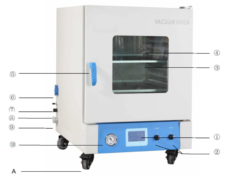
Figure 1
①Smart touch screen
② Solenoid valve of vacuum pump
③shelf
④ Observation window
⑤ Handle
⑥vacuum pump power
⑦ Inert gas inlet
⑧ Pressure balance hole
⑨ KF25 flange vacuum port
⑩ Vacuum gauge
A- Mobile casters (only 90 l and above machine)
4.2 Specifications
| Product name | Vacuum Oven | ||||
| Model | BOVA-5801 | BOVA-5802 | BOVA-5803 | BOVA-5804 | BOVA-5805 |
| Chamber Volume | 24L | 51L | 91L | 125L | 210L |
| Temperature Range℃) | Amb+10℃~200℃ | ||||
| Temperature Range (℉) | Amb+18℉~392℃ | ||||
| Temperature Stability | ±1℃/±1.8℉ | ||||
| Temperature Resolution | 0.1℃/0.1℉ | ||||
| Max. degree of vacuum | 133Pa | ||||
| Shelves | 2 | 2 | 3 | ||
| Work chamber material | stainless steel | ||||
| Maximum of Shelves | 3 | 5 | 6 | 10 | 13 |
| Interior Dimension (W*H*D, mm) | 300*275*300 | 415*345*370 | 450*450*450 | 500*500*500 | 600*600*600 |
| Exterior Dimension (W*H*D, mm) | 445*590*505 | 580*670*594 | 610*774*721 | 660*774*824 | 760*924*874 |
| Max. load | 20Kg | ||||
| N/W | 60 | 95 | 145 | 175 | 245 |
| Inert gas air inlet | Yes | ||||
| Electrical Requirement | AC220V/50-60Hz | ||||
| Power Consumption | 700W | 1400W | 2000W | 2400W | 2800W |
Table 1
4.3 Summary of structure and function
The vacuum drying oven (hereinafter referred to as the vacuum case) is of a bench structure. The vacuum case consists of four parts: case, inner chamber (working chamber), vacuum pumping system and temperature control system.The case is made of quality thin steel sheet, with the surface sprayed with plastics in bright color. The inner chamber is generally made of general galvanized steel sheet or 304 stainless steel sheet. The inner chamber is in a square of semi-circle corners and super-fine mineral wool is filled in between the inner and outer case as heat insulating material; in the door is the bulletproof glass OBW (Observation Window), for the sake of observing the articles dried in the case; on the inner side of the case installed is one piece of thick armored glass as well as the slide bush is used for connection of the door so that with slide push plus spring the armored glass and door seal can have an even stress and the case door can be pressed firmly to the rubber O-ring upon closing, without any air leakage in vacuum.
The vacuum pumping system is composed of vacuum pump (optional part), vacuum meter, vacuum valve and balancing opening. According to the needs of users, it can be equipped with the dry filtering tank (filter) or provided with air inlet as an option (through which other gas can be input into the working chamber). If the vacuum pump is selected at the user’s discretion, the pumping rate of the vacuum pump must be ≥ 2L/s
The temperature controller is the main apparatus of the temperature control system, which is a double-row LED MC smart controller composed of single chip unit and peripheral circuit. Pt100 platinum resistance is used as the temperature-sensing element and PID regulating mode is used to control the heating system. The temperature control apparatus also has such functions as timing control, temperature-control error correction and deviation alarming protection.
The heaters of resistance wire substructure are used for the electric heating system, which are all mounted inside the shelf panels.
The products of the series are advantageous for high temperature control accuracy, less overshooting, less fluctuation and temperature deviation protection.
5. Temperature and timing setting
5.1 Function introduction
Fixed value mode operation screen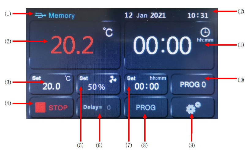
Figure 2
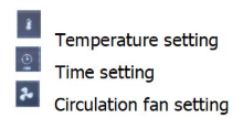
⑴: USB symbol (indicating that the U disk is connected);
⑵: Temperature measurement display area;
⑶: Temperature setting area;
⑷: Run/stop button;
⑸: The speed setting or status display window of the circulating fan in the box;
⑹: Display of scheduled boot time and display of program cycle times;
⑺: Run time setting;
⑻: Program content editing entrance;
⑼: Parameter setting entrance;
⑽: Display of running program number selection entry, current running program group number and program step number;
⑾: Running time display (countdown);
⑿: System date and time display.
Note: The functions of this window are different for devices with different functions, so we won’t introduce them in detail here. If the fan speed setting window pops up when the window area is touched, it means that the device has the function of manually setting the circulating fan in the box. Set the fan speed, which are high speed (100%), medium speed (75%), and low speed (50%).
5.2 Program mode operation screen
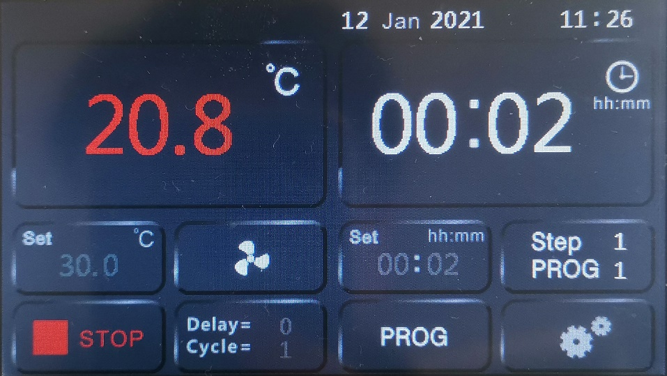
Figure 3
5.3 Operation mode selection
1. Ensure that the controller is in a stopped state2. Operation steps, as shown below: Select number 1-8, which means program operation mode
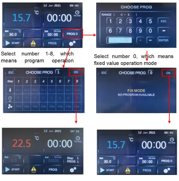
Figure 4
5.4 Program content editing
1. Ensure that the controller is in a stopped state.2. The operation steps are as follows: select the program group number to be edited
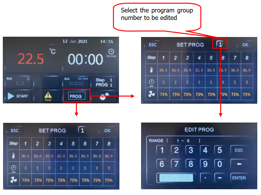
Figure 5
3. Setting of the number of program cycles
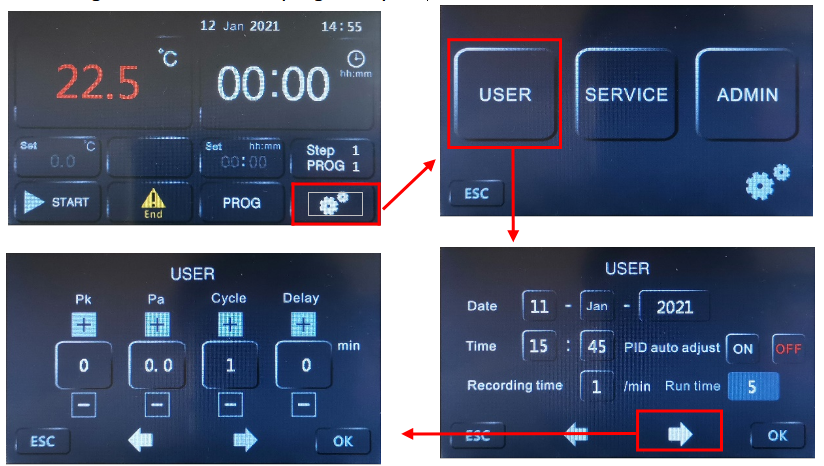
Figure 6
Cycle: The number of program cycles, 0 means infinite cycles, other numbers, the corresponding number of cycles, such as 1, if the program only runs once, the device stops.
Delay: Make an appointment to set the boot time. After setting the time here, return to the main interface and click the run button to start timing. After the time is up, the device will automatically run.
Explanation: 1. This controller has 8 groups of programs, each group of 8 steps, only need to set a stable target temperature value and the time needed to stabilize. For example: using the second set of programs, 100°C, constant temperature for 2 hours, fan speed 75%, 150°C, constant temperature for 4 hours, fan speed 100%, set as shown in the figure below:
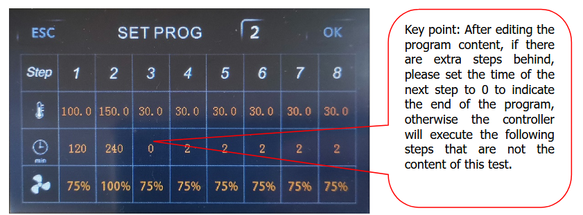
Figure 7
2. This controller is a general-purpose controller. If you find that there is no fan speed setting column in the program editing, it means that you have purchased equipment that does not have the function of adjusting the speed of the circulating fan.
3. To run in the program mode, you must have the correct program content and the number of program cycles you need to effectively meet your test requirements.
5.5 Fixed value mode operation
1. The program number is selected as 0.2. The operation is shown in the figure below:
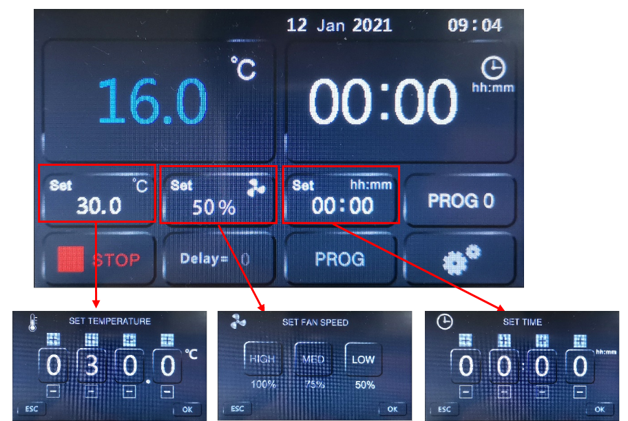
Figure 8
5.6. Schedule boot settings
1. Ensure that the controller is in a stopped state.2. Ensure that the system time is set correctly.
3. See the third step of program content editing: setting the number of program cycles
4. After the delay time is set, return to the main interface, click the run button, the main interface is displayed as follows
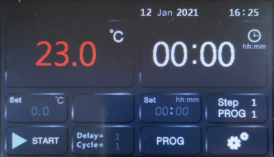
Figure 9
Note: 1. Delay = 1 means the device will start to run after a delay of 1 minute.
2. After the scheduled operation ends, the scheduled start-up delay time is reset to 0. If you want to schedule the start-up operation again, you need to perform the setting again.
5.7. Operation precautions
1) After each use, turn off the power;2) If it is not used for a long time, the cabinet must be cleaned inside and outside, and the plastic dust cover on the power plug must be removed;
3) If the storage environment has high humidity, it should be energized and heated up regularly (about 1 month) to dispel moisture;
4) Before reuse or when the process requirements change, the temperature control accuracy should be checked;
5) In addition to the temperature setting, time setting, program setting and other parameters that can be changed, other function menu parameter adjustments need to be approved by our company's service center or operated by professionals.
6. Maintenance and attention
① After using each time, power off and open the balance opening, wait for the vacuity to return zero before opening the case door (if it cannot be opened, wait for 5 minutes before opening again; opening by force may damage the door handle)② During the process of running, as for the vacuum pump, follow the principle: to run, turn on the vacuum pump before opening the vacuum valve; before stopping, close the vacuum valve before turning off the vacuum pump to prevent the vacuum pump oil from backflow into the chamber.
③ To take the articles for drying, make sure to be careful and avoid any scald.
④ In order to prevent the dried article from becoming, upon drying, the article with light weight and small volume (as small particles) or dust in the working chamber, which may enter through the air extraction port to damage the vacuum pump (or electromagnetic valve) in the process of vacuuming. The product is provided with the filtering net to the vacuuming port at the bottom inside the working chamber, which the user is requested to clean frequently to avoid affecting the effect of air extraction.
⑤ In case of stopping to sue for long, make sure to clean the product in and out, pull out the power plug and cover the anti-dust cover.
⑥ If the environment for storage is highly humid, it is necessary to regularly (about 1 month) to power on for heating up and dehumidifying.
⑦ Before using again or technical requirements are changed.
⑧ The parameters in ENGINEER SETUP menu inside the controller shall be adjusted subject to the consent of the Service Center of the company or by the professionals.
⑨ The aged door seal strips will cause improper sealing of the case and shall be replaced generally every six months.
7. Troubleshooting
| . Failure phenomena | Possible reasons | Treatment |
| No power | The out power socket had no power, | Check whether the lines are connected well and whether the socket is well. |
| The power plug is not inserted well in the socket or the line is cut off. | Re-insert the plug or repair the line. | |
| The fuse is broken or there is no fuse. | Check whether there is any short circuit; replace the fuse (short circuit for apparatus power transformer, short circuit for heater, short circuit for grounding and others short circuit all can cause breaking of fuse. | |
| PV display ”□□□□” | Temperature sensor Pt100 is damaged | Check Pt100, replace it |
| Temperature sensor line is not connected well. | Connect lines again. | |
| The temperature does not increase The temperature does not increase | Test scope of the apparatus is not correct | Re-set again. |
| The set value is too low | Set temperature SV≥RT+18℉ RT is environment temperature | |
| The output circuit of the apparatus is falling off. | Connect the lines again. | |
| Temperature controller has no output signal or is damaged or the controllable silicon is damaged, | Replace it. | |
| The heater is damaged(short circuit, or open circuit) | Replace it. | |
| The temperature is out of control , the deviation and between tested temperature and measured temperature The temperature is out of control or there is offset or overshoot because of the error between tested temperature and real temperature | Use timing function or the setting is not correct. | ST=0 or ST=(heating time +constant temperature time |
| The output of temperature controller is out of control. | Replace SRC | |
| Pt sensor doest connects well. | Get rid off grounding resistance. | |
| Relevant parameters are not correctly set. | Re-set relevant parameters, such as P and so on. | |
| There is big difference between tested temperature and real temperature. | No vacuum situation. | Vacuumizing. |
| The mercurial thermometer head is not on the shelf. | Replace it. | |
| The apparatus or parameter is changing. | Re arrange Pb、Pk parameters. | |
| The cabinet cannot be vacuumized. | The vacuum pump is not of the correct model and size. | The vacuumizing speed should not be less than 2 L/S. |
| Various connecting pipe is too loose. | Replace it. | |
| The vacuum meter is damaged. | Replace it. | |
| The door is not closed well. | Adjust the door pin distance. | |
| The door airproof rubber is aged and lack of elasticity. | Replace it. | |
| Air release valve and vacuum vale is not in the correct place. | Adjust them. | |
| Air leakage (the vacuum degree decrease to 0.092 Mpa from 0.1Mpa within 24 hours. | There is air leakage in various connect pipes. | Check and replace it. |
| the distortion of heater ”O” shaped airproof circle causes air leakage. | Screw tight the heater seat (in the back of the inner bladder.) or replace “0” shaped airproof circle. | |
| The air release valve is not in the right place. | Place it in the right place. |
Table 2
Common degree of vacuum unit conversion table:
| Conversion value Item Unit | KPa | 〃Hg | mmHg | Atm | allowable deviation |
| 1(bar) | 100 | 29.53 | 750 | 0.987 | ±2.5% |
Table 3