


Microplate Reader BMRW-101
- Sea, Air, Door to Door Shipping
- 1 Year Warranty
- US & European Standards
Microplate Reader is a laboratory instrument that is used to measure chemical, biological or physical reactions, properties and analytes within the well of a microplate. Flexibility and reliability makes this product an unique choice.
- It is an eight-channel reader with the most sophisticated technology, high quality, high reliability and easy to operate.
- 8 channels measuring system.
- Analysis Mode: Cut-off, single and multi-stnadard, O.D. ,bichromatic, dynamic reading.
- Optical fiter 405/450/492/630nm
Specification
Features
Applications
| Measuring System | Optical system with 8 channels |
| Analysis Mode | Cut-off, single and multi-standard, O.D.,bichromatic, dynamic reading |
| Linear Range | 0.001-3.500 Abs |
| Photometric Accuracy | ±1% or ±0.001 Abs |
| Repeatability | <1.0% |
| Stability | <0.005 Abs/hr |
| Linearity | <±1.0% |
| Sensitivity | ≤±0.001A |
| Channels Discrepancy | ≤±0.002A |
| Optical Filters | 405/450/492/630 nm other filters available on request |
| Reading | Automatic focusing function makes the results more precise |
| Tray Shaking | Yes |
| Storage | 100 programs |
| Display | Touch screen |
| Interface | RS-232 and USB port |
| Printer | Built-in thermal printer (external printer are available on request) |
| Power Supply | AC 220V 50 Hz or 110V 60 Hz |
| Dimension | 46Lx33Wx18H cm |
| Weight | 7.5 kg |
- It is an eight-channel reader with the most sophisticated technology, high quality, high reliability and easy to operate.
- 8 channels measuring system.
- Analysis Mode: Cut-off, single and multi-stnadard, O.D. ,bichromatic, dynamic reading.
- Optical fiter 405/450/492/630nm
- 100 programs storage.
- Touch screen display.
- Built-in thermal printer.
Life Science, Drug Discovery, Research, Laboratory, Medical, Assay Development
Operating Manual for BMRW-101
1. Important Safety Instruction
1.1 Read the followings before using the instrument
1.2 Symbol
2. Introduction of instrument
2.1 Application Scope
2.2 Main Performance
2.3 Main Function
2.4 Main Structure and Components
2.5 Specification and Technical Parameter
3. Instrument Installation
3.1 Instrument Packaging and unpacking
3.2 Environmental Requirements
3.3 Transportation and Storage Conditions
3.4 Service Life and guarantee
3.5 Power Supply Requirements
3.6 Start installing
3.7 Print paper installation
3.8 Notice and direction of sample collection and handling
4. Input Tool and Operation
4.1 Touch Screen&pen
4.2 Digital soft keyboard
4.3 Character soft keyboard
4.4 Date time soft keyboard
4.5 Formula soft keyboard
5. Start-up
5.1 Procedure of start-up
5.2 Main Menu
6. System
6.1 Main Menu
6.2 Data Delete
6.3 Dictionary
7. Item Setup
7.1 Measure method
7.2 Analysis method
7.3 Add New Item
7.4 Modify the item
7.5 Delete the item
8. Test
8.1 Test setting
8.2 Plate Well
8.3 Templet
8.4 Well Position
8.5 Plate test
8.6 Result view and print
9. Sample Information
9.1 Basic operation
9.2 Sample(Patient) information
10. Search
10.1 Sample(Patient) data searching
10.2 Item Report
10.3 Board Report
10.4 Standard Curve
11. Report
12. PC Control
12.1 Software installation
12.2 Software running environment
12.3 Software serial communication protocol and code
13. Shut down
14. Instrument maintenance
14.1 Summary
14.2 Cleaning instrument
14.3 Instrument parts replacement
14.4 Simple fault handling
1. Important Safety Instruction
Dangerous or wrong using method may cause electric injuries, burns, fire or other disaster.Basic safety protection including all the followings should be always obeyed.
When the instruments are used near children, disabled people or samples, rigorous monitoring should be performed.
1.1 Read the followings before using the instrument
1) Check correspondence of voltage equipment and supply voltage.2) Connect with network source: Put the instrument plug in the socket which has a grounded power cord.
3) Take the plug out after finishing operating the instrument. Do not place the instrument in a difficult position to operate the disconnecting device.
4) You mustn’t put the instrument in or near liquid. If the instrument is wet, please take the plug out before touch it.
5) Please do not leave the instrument alone when it is working.
6) The instrument can only be used for tests according to the manual.
7) Do not use spare parts which are not provided or suggested by the manufacturer.
8) If the instrument is in abnormal working position or damaged, do not operate it.
9) Do not make instrument and lines touch surfaces which are too hot.
10) Do not block vents. Make vents away from soft cloth, fur, lint etc.
11) Do not put anything on the instrument.
12) Unless special requirements of the manual, you can not put anything into opening, pipe or seam of the instrument.
13) Do not use instrument in the place where exits aerosol, droplet or oxygen is controlled.
14) Do not use instrument outdoors.
15) When dealing with hazardous substances, it should be handled by professionally trained personnel.
16) Keep far away from electromagnetic interference sources.
17) Avoid direct exposure of high light.
18) Manufacturers are responsible for providing electromagnetic compatibility information of equipment to customers or users.
19) The user has the responsibility to ensure the electromagnetic compatibility of the equipment, so that the equipment can work properly.
20) In dry environments, especially in the drying environment of artificial materials (artificial fabrics, carpets, etc.), the use of this equipment may cause damage to electrostatic discharges, resulting in erroneous conclusions.
21) Prohibit the use of this device near a strong radiation source (such as a non shielded radio frequency source), or it may interfere with the normal operation of the equipment.
22) This equipment is designed and tested according to class a equipment in GB4824. In the home environment, this device may cause radio interference and requires protective measures.
23) It is recommended that the electromagnetic environment be evaluated prior to the use of the equipment.
24) This equipment complies with the emission and immunity requirements specified by GB/T18268.26.
 Note: The instrument used reagents and samples may be corrosive or infectious, please pay attention to the protection of instrument when do the operation, can use protective gloves, do not come into contact with the skin, the waste must be in strict accordance with the management of medical waste treatment system. Note: The Microplate Reader is very professional precision instrument, the equipment maintenance must be conducted by professional staff .When maintenance, repair, or movement should do the cleaning and disinfection of instruments so as to minimize biological hazards, the company promises to respond to user needs at any time, don't agree with non-professional personnel engaged in the work related to the maintenance, repair, our company is not responsible for the consequences.
1.2 Symbol
The following table lists the symbols used on the Microplate Reader and their significance.| Symbols | Significance | Explain |
| Be careful, dangerous | Identify the machine where you need to be careful and make sure that you read the relevant contents of the operating manual before using the machine. |
 | Biological hazards | The symbol is marked on the machine to indicate that a device is potentially contagious due to a sample or reagent used. |
 | Serial number | The symbol is marked on the machine to indicate the serial number of the machine. |
 | Vitro diagnostic medical device | The symbol is marked on the machine to indicate that the device is an in vitro diagnostic medical device. |
 | Protective conductor terminal | The symbol is marked to indicate ground protection. |
 | Equipotential | The symbol is marked on the machine to indicate ground. |
 | Through (power) | The symbol is marked on the machine power switch to indicate instrument power on. |
 | Break (power) | The symbol is marked on the machine power switch to indicate instrument shutdown. |
 | Manufacture Date | The symbol is marked on the machine nameplate to indicate the date of manufacture . |
 | Service life | The symbol is marked on the machine nameplate to indicate the period of use of the machine. |
Table 1
2. Introduction of instrument
2.1 Application Scope
Microplate Reader is applied in clinical optical method for enzyme-linked immunosorbent assay.2.2 Main Performance
Wavelength accuracy and transmission character of the filters should meet the following requirements:| Item | Indicator |
| Indication error of wavelength(nm) | ±1.0 |
| Half width(nm) | ≤8 |
| Peak transmittance(%) | ≥35 |
Table 2
-Measured value stability:±0.003A
-Absorbance indication error (Accuracy):±0.008A
-Absorbance repeatability: ≤0.2%
-Sensibility:≥0.01(L/mg)
-Channel error: ≤0.01A
2.3 Main Function
-Large screen interface, touch screen and touch pen input mode make it convenient for users to inputinformation.
-More than 500 programmable laboratory tests.
-Four measurement method: Single wavelength, Double wavelength, two point method, kinetic
-Several quantitative and qualitative methods: ABS, Cut-Off regression,Single-point calibration, broken line regression, linear regression, exponential regression, logarithm regression, double logarithm regression, log-logit, power regression.
-96-well visual plate. Blank hole, contrast hole, sample hole, standard hole and quality control hole are adjustable.
-Conduct 12 different tests in one plate at the same time.
-Fast and accurate testing with 8 channels (≤10S/ Plate ) .
-Flexible synthesis report output, supporting internal thermal printer and printer with USB interface
2.4 Main Structure and Components
The instrument is made up of switch power supply, optical path system, inner computer system and sample transmission system.Front view:
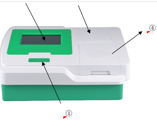
Figure 1
① Power indicator light : After the instrument is power on, the indicator light is lit.
② Touch screen: Show software interface. Users can press the screen with fingers for variable operation
③ Internal thermal printer: Plastic cover plate. Paper delivery when using internal thermal printer. You can open the cover plate to replace paper.
④ ELISA plate cover plate: Plastic cover plate. Prevent dust from polluting inner space of ELISA plate and instrument.
2.5 Specification and Technical Parameter
| Net Weight: | 8 kg |
| Dimension: | 475mm(L)×340mm(W)×200mm(H) |
| Power supply: | AC 100V~240V, 50/60 Hz |
| Fuses: | F2AL 250V |
| Working environment: | Environment temperature:+10℃~+30℃;Relative humidity: 30%~80%;Atmosphere range:70kPa~106kPa;Power supply:AC 100V~240V, 50/60 Hz;Transient over-voltage is classified as device class (over-voltage) class-Ⅱ;Rating pollution level is classified as class-Ⅱ. |
| Storage temperature: | -10℃~+55℃ |
| Light source: | Quartz halogen lamp OSRAM64607,8V/50W |
| Wavelength: | 405nm,450nm,492nm,630nm,add at most 4 filters with wavelength between 400 nm and 850 nm. |
| Measuring range: | 0.000~4.000A |
| Reading speed: | Single Wavelength ≤ 3s,Double Wavelength ≤ 6s |
| Warm-up time: | 10 minutes |
| Computer system: | ARM core series |
| Programming items: | More than 500 |
| Communication interface: | RS-232 serial、Parallel printer、USB、Mouse and keyboard interface |
| Display: | LCD display screen |
| Input mode: | Touch Screen ,Touch pen |
| Memory Capability: | 200,000 test data |
Table 3
3. Instrument Installation
3.1 Instrument Packaging and unpacking
Unpack the instrument package, and take out the instrument. Check items in the package according to PACKING LIST: main instrument, power line, fuses, touch pen, instruction manual, packing list, verify report ,dust guard ,PC software CD and so on .Note: The AC power supply must be well grounded (protective grounding voltage<5V)Internal protective grounding of the machine unified using with logo .The AC power supply must be stable, don’t share power with high-power electrical appliances. When unplug the power line,, must grasp the plug itself, rather than the power line. If discover there is smoke, strange smell or strange sound, immediately shut off the power and contact the seller.
3.2 Environmental Requirements
Choose flat worktable which is enough to place the instrument and without direct sunlight.Instrument working environment:
1)Temperature: +10℃~+30℃
2)Relative humidity: 30%~80%
3)Atmosphere range: 70kPa~106kPa
4)Power supply: AC 100V~240V, 50/60 Hz
5)Transient over-voltage is classified as device class (over-voltage) class-Ⅱ, Rating pollution level is classified as class-Ⅱ.
6)Good ventilation and no corrosive substances.
To insure normal operation of the instrument, you mustn’t put instrument in the following places: temperature polarization, extremely hot or cold, with a lot of dust, near electromagnetic equipment.
3.3 Transportation and Storage Conditions
Transportation condition: Transportation should meet the requirements of the instrument and package indication. Customers should check whether the package and instrument is OK when receiving goods. If any problem, customers need turn on the instrument to see if it works.Ship & storage condition: The instrument should be stored in a room with temperature -10℃~+55℃, relative humidity less than 93%, atmosphere range is 70kPa~106kPa ,good ventilation and no corrosive substances.
3.4 Service Life and guarantee
Service life: 5 yearsService guarantee: 1 year warranty and life-long maintenance.
3.5 Power Supply Requirements
Power supply voltage: AC 100V~240V, 50/60 HzInput power: 150VA.
Note: The AC power supply must be well grounded (protective grounding voltage<5V)Internal protective grounding of the machine unified using with logo
 .The AC power supply must be stable, don’t share power with high-power electrical appliances. When unplug the power line,, must grasp the plug itself, rather than the power line. If discover there is smoke, strange smell or strange sound, immediately shut off the power and contact the seller.
3.6 Start installing
--Connect instrument to power source;--Put one port of power line in power socket of the instrument ;
--Put the other port of power line in AC power socket.
3.7 Print paper installation
3.7.1 Press the printer cover plate, then remove the printer cover (figure 1).3.7.2 Pull out of the printer roller and place the printer paper thermal surface down to the head direction of printer . Press the printer roller (figure 2-3).
3.7.3 Put the printer paper out of printer cover plate, cover the plate (figure 4).

Figure 1
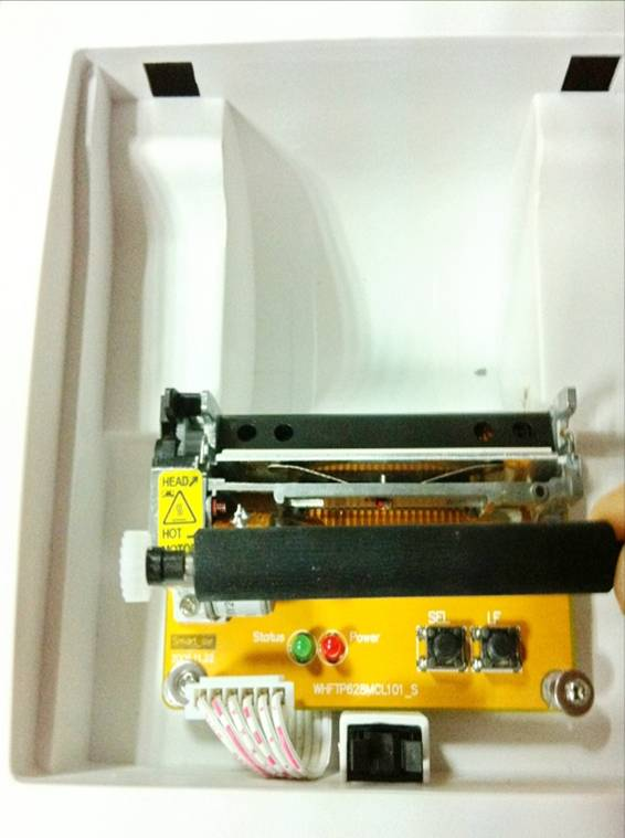
Figure 2

Figure 3

Figure 4
Note: 1. When pull the printer roller, pull in the middle.
2. When installing the printer roller, first install the gear side.
3.8 Notice and direction of sample collection and handling
The most common sample of inspection is blood, which includes serum, plasma and whole blood. Sometimes saliva and urine are also tested as sample. Sample collection should obey clinical blooding technology standard in principle, unless special requirements in the kit instruction.Sample collection:
• Serum sample collection: Draw a certain amount of venous blood with single-use syringe or vacuum blood tube, and place it at room temperature for 1-2 hours. Centrifuge with speed after 3000r/min more than 6 min after tarombokinesis and blood clot retraction, and suck serum in reserve. You should take care when collecting samples. It is proposed to use evacuated blood tubes or butterfly needles to collect samples, avoiding direct contact with blood.
Sample storage:
• Serum or plasma sample which are used for antibody detection should be stored in temperature below -20℃. Samples which will be tested during 1 week can be stored in temperature of 2~8℃. Plasma and blood cell samples for antigen and nuclein detection should be cryopreserved in temperature below -20℃.
Application of sample and incubation:
• Operators should use graduated transferpettors.
• When incubating, operators should check temperature and make accurate timing before put plate in incubator or water-bath.
Washing plates:
• It is best to use microplate washer to wash elisa plates, also set soak time and washing times according to reagent instruction.
• When hand washing, try to avoid cross contamination.
Color development:
• Color developing reagent should be taken out from refrigerator 10 minutes before using. When adding color developing reagent, keep dropping bottle straight down and holding pressure uniform, besides dripping speed not too fast. Do not mix reagent A and B before adding, you should add A and B in turn.
Reading plates:
• After color development, operators should use microplate reader to read the elisa plates during required time of the instructions’.
• After reading plates, operators should process sample plates as pollutant.
Waste processing
• Regard kit as infectious substance and process it according to laboratory regulation about infectious disease. ( Refer to reagent instruction’s requirements).
4. Input Tool and Operation
4.1 Touch Screen&pen
Microplate Reader uses touch screen & touch pen as basic input device. The user operates within the scope of the screen. Basic operations only have 1 kinds:(1) Click: Touch the screen with a finger or pen then leave;
Warning:
Microplate Reader use touch screen: do not use sharp or hardness of objects (such as metal, glass, nails, etc.) touch screen surface; Part of touch screen is glass, do not exert great impact on touch screen, so as to avoid damage.
The grounding of AC power supply must be good, otherwise it may affect the sensitivity of touch screen.
Note: Microplate Reader can be equipped with an external mouse, keyboard.
4.2 Digital soft keyboard
The enter window can be used to input integers (such as sample numbers, etc.), decimals (such as concentration values etc.). The enter content consists of 0~9 and decimal points. After completing enter, press the “ OK ” button to confirm ,or press “ Cancel ” button to abandon content.Change the content: Press the "Back" button to delete the first character of entered ; Press the "Clear" button to clear all the content you've entered.
The window title bar is prompted with enter content and its limits. If user enter exceeds the limit, the system will be discarded automatically. The system has the following restrictions on user enter content:
1) The value entered shall not exceed the max or min; If the min is non-negative, press the "-" button is invalid.
2)When enter an integer, press "." button is invalid.

Figure 5
4.3 Character soft keyboard
The enter window is used to input characters and alphabetic strings.The "English" button means that the current enter state is English, and the "Chinese" button means that the current enter state is Chinese, and this button can be changed with English & Chinese system.
All buttons on the soft keyboard are similar to the ordinary PC keyboard, and the "Back" button is used to delete characters, and the "Cap" button is used to switch the case of the entered letters. To cancel this entry, click the “X” button at the upper right corner.
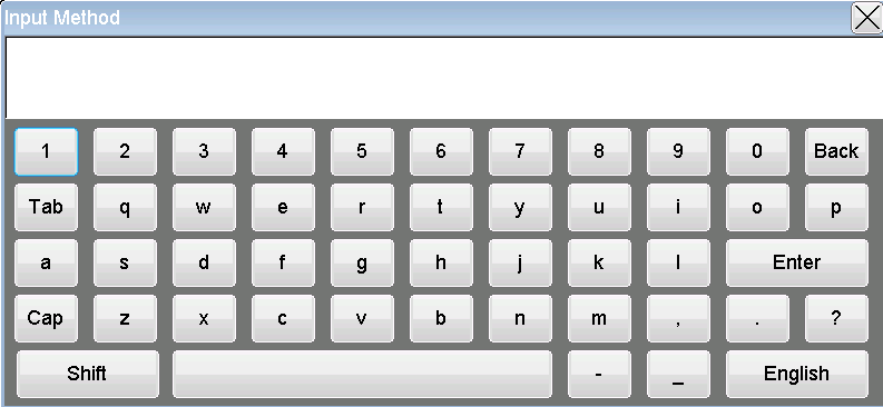
Figure 6
4.4 Date time soft keyboard
For entering date and time, sliding the number up or down can change the current selection state.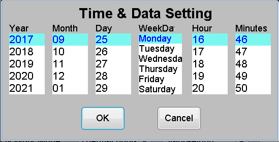
Figure 7
4.5 Formula soft keyboard
Used to enter a qualitative formula.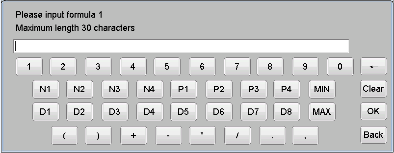
Figure 8
5. Start-up
5.1 Procedure of start-up
Turn on the power switch at the rear panel. Wait about 6 seconds, the instrument will perform an initialization process.The procedure of start-up includes:
1)Load the program;
2)Access the user data;
3)light road and mechanical self-examination: during the period, the filter wheel will rotate, and the enzyme plate will approach a round trip.
If an error occurs during initialization, the system pops up a window to report an error message. Users can refer to the "Simple fault handling" section of this manual “Instrument maintenance”. If can’t solve it, please contact the seller.
5.2 Main Menu
The screen displays the main menu after the procedure of start-up. The main menu has 8 different modes: Test,Item Setup, Report, Sample ,Search,Dictionary,System and Data Delete.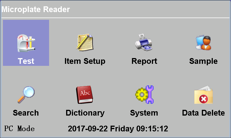
Figure 9
6. System
Click “System” button in the main menu and go into the system setting menu.6.1 Main Menu
Select the “System” button and go into the system setting menu:1) Serial No.(ID): This number is read-only and cannot be modified;
2)Company Name: No more than 20 characters (including Chinese and English characters);
3)Report Title: No more than 20 characters (including Chinese and English characters;
4) LCD& Sound: Click "<<" or ">>" to adjust the contrast of the LCD screen;
5) Sound : Click to activate or close the beep sound;
6) Regional: Modify the time display format and system language;
7) Date&Time :The current date and time can be entered;
8) Print:Select the printer model, which supports KX-P1121 needle printer/EPSON-LQ300K+ needle printer/ Built-in thermal printer;
9)Work Mode : Select Stand-Along or PC mode work;
10) Input Device : Select the current mode of operation as the Key & Mouse or Touch input;
11) Maintenance: Provides a range of system detection functions, including Add Filters, Lamp Test, Repeat Test and so on;After you modify the parameter, click “OK “ button to save the settings, and then click “Back” button to quit.
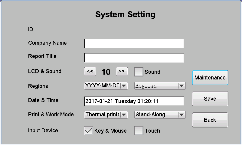
Figure 10
Click the ‘Maintenance’ button to go into the system maintenance menu.
• Add Filters: First select the number of filters, then fill each filter wavelength corresponding each well, click "OK" button.
• Lamp Test: The function is mainly used to replace the lamp. After selected the filter, click the "Start" button, and then manually adjust the position of the lamp, while observing the test value; adjust to the maximum value, fixed the lamp.
• Repeat Test: This function is mainly used for detecting instrument performance. Select filter, test times and row to test, the system will calculate the average value, CV value, and repeatability value automatically.
• Self Test: This function mainly test if the mechanical parts of the instrument can be used normally.
• Background Color Set: This function sets the background color.
• Advanced: This module is only used by the serviceman/ manufacture.
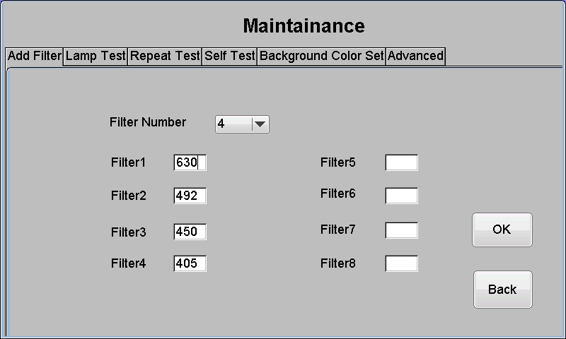
Figure 11
6.2 Data Delete
• In the main menu , click the ‘Data Delete’ button to go into the menu of data deleting. This window makes it easy for users to delete data in bulk. Select the option to delete, click “Delete”.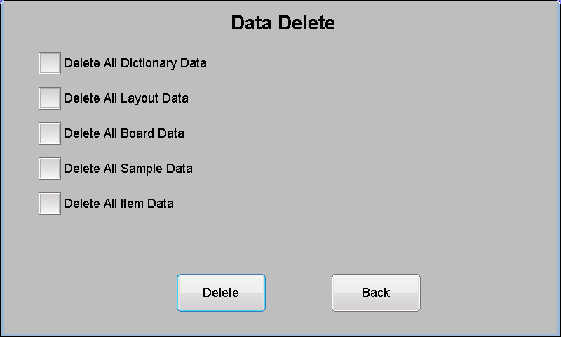
Figure 12
6.3 Dictionary
In the main menu, click the ‘Dictionary’ to go into the editing interface of dictionary.This window provides addition, modification and deletion for seven dictionary information. Including Clinical Lab, Submit Dep., Lab Doc.,Submit Doc. ,Sample,Diagnosis,Unit.
Add: Click the “Add ” button and then enter the relevant information in the soft keyboard.
Modify: First select a dictionary item then click the “Modify ” and enter the relevant information in the soft keyboard.
Delete: First select a dictionary item then click the “Delete”,delete the selected dictionary item.

Figure 13
7. Item Setup
In the main menu, press the “Item Setup” button to enter the item list window: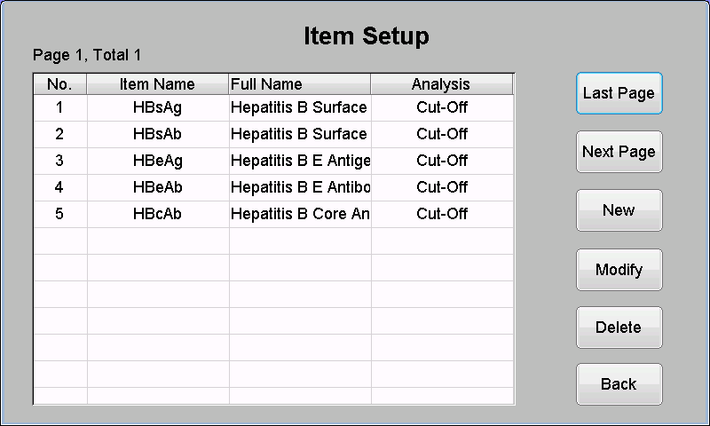
Figure 14
Microplate Reader all items are defined by the user. Items that have been set by the user are displayed in the window list.
7.1 Measure method
The reader has four measure methods.7.1.1 Single wavelength
The method uses one wavelength to measure the OD.
7.1.2 Dual wavelength
The method uses two wavelengths to measure the OD. The result of OD is the difference of the main wavelength and the second wavelength.
7.1.3 Fixed time
Absorbance values were measured at two different time points. The absorbance value is the difference between the second detection value and the first detection value.
7.1.4 Kinetics
The absorbance was measured several times according to the interval between the intermittent time and the delay time. According to the slope of the absorbance curve obtained by the regression, the absorbance value of 1 minutes was used as the absorbance value, and the concentration value was calculated.
Note: the kinetic method uses only one wavelength.
7.2 Analysis method
There are 9 analysis methods, divided into the following 3 categories:7.2.1 O.D. mode
The absorbance of the sample is measured and output directly.
7.2.2 Qualitative(Cut-Off) mode
Cut-Off limit formula:

NC is the O.D. of the negative reference material,PC is the O.D. of the positive reference material,X,Y,Fac is the coefficient,which is set in the reagent instruction. All the other kind of qualitative formula can convert into this formula format. For example:if Sample OD/Negative Ref.OD≥2.1 is the Positive, then X=2.1,Y=0, Fac=0。
The result of qualitative calculation is expressed by the ratio of sample absorbance to cut-off threshold, the unit is s/co. Generally, the value of negative and positive is determined with 1 as the critical value.
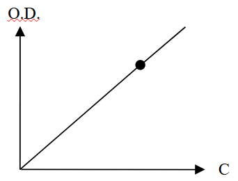
7.2.3 Quantitative mode
Single regress:need to set 1 standard, take the line of origin and standard point as the calibration curve. Single regress must set blank to calibrate 0.(X:concentrate,Y:O.D.):
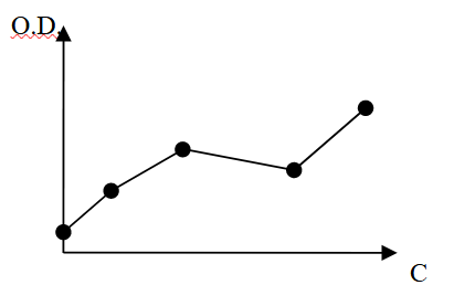
1. Multi regress(point - point) :allow set 2-8 standard samples ,take each standard point as the calibration curve (should be a monotonically ascending or downward fold) :
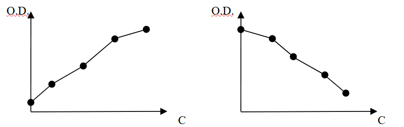
If the absorbance of the standard sample does not increase monotonically or decrease monotonically, the calibration result is error:
2. Linear regress:allow set 2-8 standard samples,a straight line
 is regressed by these standard points as a calibration curve:
3) Exp. Regress:allow set 2-8 standard samples,an exponential curve
 is regressed by these standard points as a calibration curve,all the standard sample O.D. values must be >0 .
If the absorbance value is logarithmic (
 ), the exponential regression can be transformed into linear regression:.
4) Log Regress:allow set 2-8 standard samples,a logarithmic curve
 is regressed by these standard points as a calibration curve,all the standard sample concentration values must be >0 .
If the concentration is logarithmic (
 ), the logarithmic regression can also be transformed into linear regression:.
5) Dual Log:allow set 2-8 standard samples,a double logarithmic curve
 is regressed by these standard points as a calibration curve,all the standard sample concentration values must be >0 .
If the concentration is logarithmic (
, ), the logarithmic regression can also be transformed into linear regression: 
6) Power Regress:allow set 2-8 standard samples,a power curve
 is regressed by these standard points as a calibration curve,all the standard sample O.D. values and concentration values must be >0 .
7.3 Add New Item
Click the “Item setup” icon in the main menu and go into the item list window.Select“New” to add new item。
The parameter of the item setup:
● Item Name : Item name, string including 20 characters at most,blank unallowed;
● Full name: Item full name, string including 20 characters at most, blank allowed.
● Reagent: Reagent name, blank allowed.
● Method: Select the test method from four methods.
● Main/Second Wavelength: Select from the wavelength list,and the second wavelength should be different with the main wavelength;
● Wait Time:Fixed time method and kinetic method need to fill the wait time, ranging from 10 to 120 seconds.
● Test Times: Kinetic method need to fill the test times, ranging from 2 to 10 times.
● Analysis: Different type analysis methods, selected from the list of methods.
● Sample type: Can select one from Single Sam/Double Sam/Column minus. Double Sam is the average value of two samples , Column minus is the difference between two samples .
● Blank Max.:Define the max. value according to the the reagent blank. For example, the reagent needs the blank less than 0.05,then the blank must be ≤0.05. If the blank O.D. is larger than the max blank, “The blank value is too high”will appear and the maximum blank is used as the blank automatically.
Blank : The blank contrast absorbance value of the actual test.
● Ref. Area: The scope of the calculation results of the item. Some items can be entered 0.000 ~ 0.000 if the user does not need to print the reference range.
● Sort No.: Define the sort of the item in the patient report. The small No. is in the front of the list. The default value is 100.
● ABS analysis methods:Press the “OK ”to save the item information and press the “Cancel” to exit the settings for the current items;
In addition to ABS, other calculations can be found on “page 2”, “page 3” and “page 4".
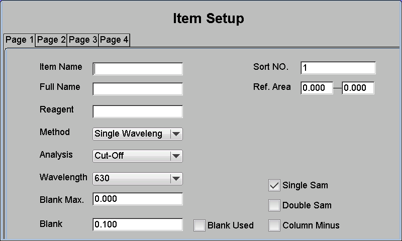
Figure 15
If the analysis method is Cut-Off, click “Page 2” to view the menu:
● Negative/Positive Ref Area:The valid reference area of the Negative and Positive,the default value is 0.000~4.000;
● Negative/Positive 1~4:User can see the OD of the Negative/Positive after test, or set the OD directly without test. Then click “Page 3” .
● Qualitative Group Name:User can define the name or signal of every group;
Click the label “Group 1”~“Group 5” to set the predefined name,which will shift between the “Negative,Weak negative, Grey Area,Weak positive, Positive”;
● Formula(Cut-Off value):User can define the C.O. formula or value of every group, four formulas at most;
The relation of the Cut-Off value、OD value and qualitative is:

From the manual of the ELISA kit, the formula of the Cut Off is “Cut Off value=Negative × 2.1”, so the formula should be 2.1*NC1;If there are comments like“Minimum Negative OD = 0.05 ”,the meaning of the comments is to get the large value of the NC1 and 0.05,so the final C.O. formula is:
2.1*MAX(NC1,0.05)
This is the formula of the Group 1. There are four formulas at all. And the value of the formula must be “Formula 4 >Formula 3> Formula 2> Formula 1”. The five groups have four formulas.
If the item has more formulas, the CO value in S/CO could be selected from the four formulas. The default value is 1.
If the formula is longer than the viewing area, just click the formula before the group label to show the full formula in the last line.
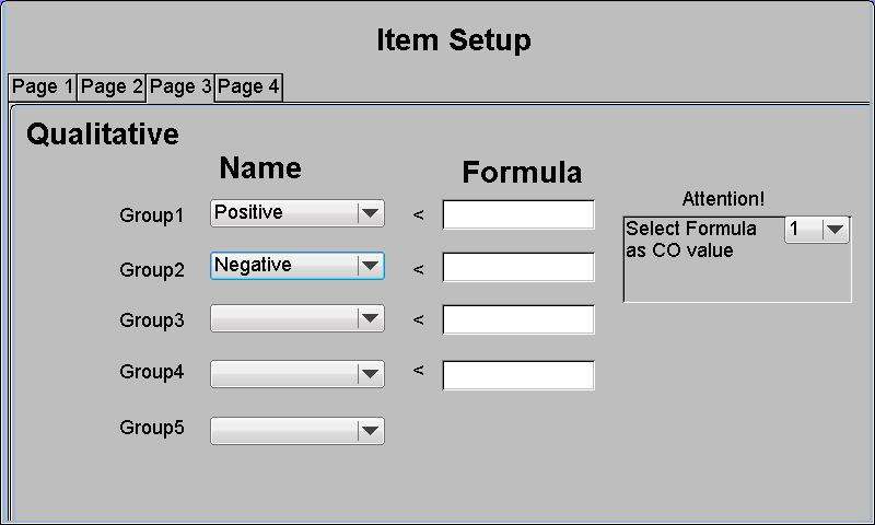
Figure 16

Figure 17
n addition to the formulas Cut-Off and ABS, click the “Page 2” to display the quantitative settings interface, and you can modify the following parameters:
● STD numbers: In addition to Single regress only can set 1 standard samples ,others can set 2~8 standard samples.
● Dilute Multiple:Define the dilute multiple of the sample, and the calculated value should multiply the dilute multiple.
● Unit: Choose unit from the 24 common units in the list.
● Dual STD: If check the dual STD,all the standards in the plate will be positioned double times.
● ABS percent: Check the box to use
 as the ordinate of the standard graph,the D0 is the reference standard of 100% O.D., and the D0 needs no concentrate. If the item selects the ABS percent, the first standard is D0 when position the plate. The dual logarithm regression cannot use the ABS percent because of the ordinate is in logarithm.
● STD concentrate table: Display and select the STD concentrate. Attention: All the STD concentrate should increase.
● Modify concentration: Modify the selected concentration.
Then click “ Page 3” .
● Qualitative Group Name:User can define the name or signal of every group;
Click the label “Group 1”~“Group 5” to set the predefined name,which will shift between the “Negative,Weak negative,Grey Area,Weak positive, Positive”;
● Formula(Cut-Off value):Users can define values or formulas for each grouping, while supporting multiple formulas.

Figure 18
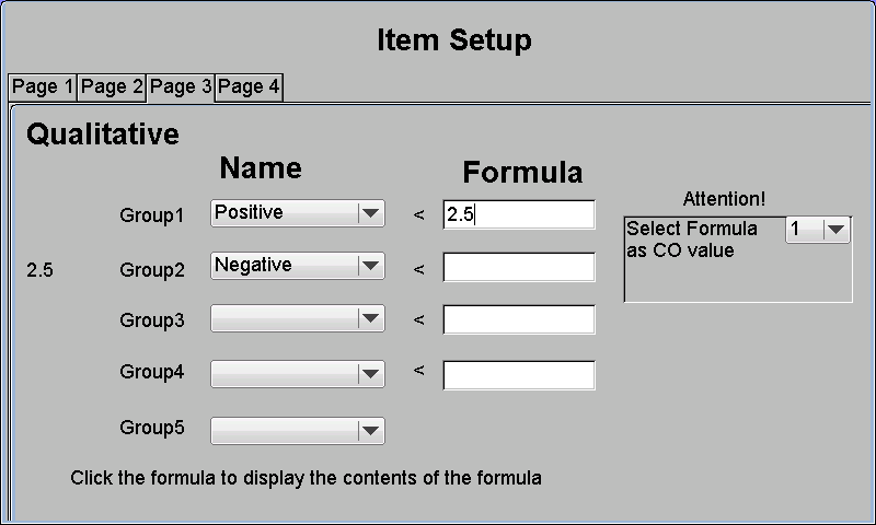
Figure 19
When adding a new item, the new item will not be created if the items number has exceeded 500, the system prompts that “The number of items is full”. The operation of adding a new item is the same as the procedure for changing an old project. Note that the name of the new item entered cannot be repeated with the existing item, otherwise the system will warn that “The item already exists".
7.4 Modify the item
Select an item from the list and click the “Modify” key to modify the item setting.After the Cut-Off items is modified, the values of each contrast are retained and the CO values are recalculated. (this product supports multiple formulas).
After the quantitative items are modified, the absorbance values of each standard are retained and the curves are re plotted.
Note: When the number of standard samples or contrast negative /positive changes, the standard samples absorbance and the curve , all CO values will be removed.
7.5 Delete the item
Select an item from the list and click the “Delete” key to delete the item.Note: Do not delete items that have been built and tested at will, otherwise it will cause errors in saved data! To delete certain items, make sure that no data is saved in the system. (You can delete data in the data deletion module first)
8. Test
8.1 Test setting
Click the test button on the main screen and enter the test parameter settings window.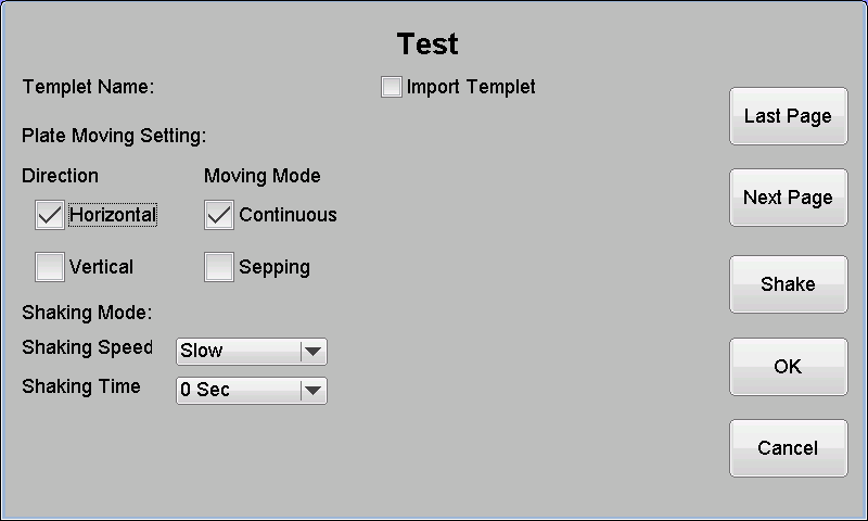
Figure 20
● Plate Direction:select Horizontal or Vertical position;
● Moving Mode:select the plate continuous moving or stepping moving;
● Shaking speed:select the slow、medium or fast shaking speed;
● Shaking time:select the time of shaking plate, user-defined area is from 10 to 180 second.
● Import Templet: You can import the default layout template.
● Shake:Separate shake plate and mix the sample to be tested.
8.2 Plate Well
| * | 1 | 2 | 3 | 4 | 5 | 6 | 7 | 8 | 9 | 10 | 11 | 12 |
| A | A1 | A2 | A3 | A4 | A5 | A6 | A7 | A8 | A9 | A10 | A11 | A12 |
| B | B1 | B2 | B3 | B4 | B5 | B6 | B7 | B8 | B9 | B10 | B11 | B12 |
| C | C1 | C2 | C3 | C4 | C5 | C6 | C7 | C8 | C9 | C10 | C11 | C12 |
| D | D1 | D2 | D3 | D4 | D5 | D6 | D7 | D8 | D9 | D10 | D11 | D12 |
| E | E1 | E2 | E3 | E4 | E5 | E6 | E7 | E8 | E9 | E10 | E11 | E12 |
| F | F1 | F2 | F3 | F4 | F5 | F6 | F7 | F8 | F9 | F10 | F11 | F12 |
| G | G1 | G2 | G3 | G4 | G5 | G6 | G7 | G8 | G9 | G10 | G11 | G12 |
| H | H1 | H2 | H3 | H4 | H5 | H6 | H7 | H8 | H9 | H10 | H11 | H12 |
The direction of the plate’s moving is ←——。
8.3 Templet
Click the “Import Template” button to display the template selection window.
Figure 21
elect an existing template and click “OK “to import the template.
Contains all of the information in the template layout: layout direction, moving mode, item no ,type.
8.4 Well Position
Click "OK" button, enter the test setup layout window .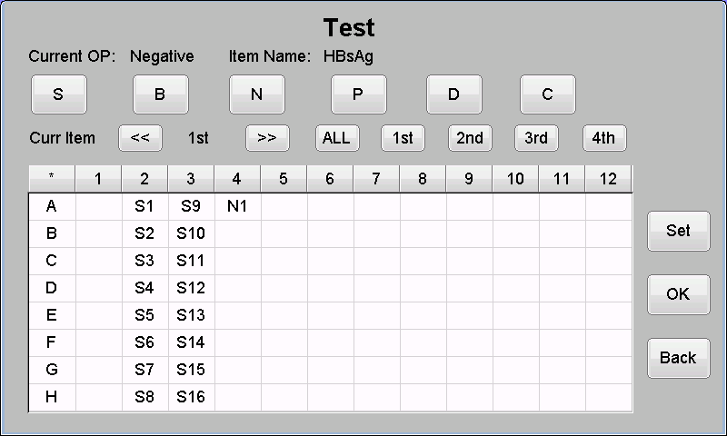
Figure 22
The Microplate Reader allows users to set wells at any position within the 96 orifice plate.
-The procedure of the position:
a) Click “Set” to select the item;
b) Click “S,B,N,P,D,C” to select the type of the sample;
If you need multi item board layout., click on the "2nd" or ">>" button, select the item and layout again. Repeat the steps until the completion of the board layout.
Well mark symbol:
● Sample:S
● Blank:B
● Negative contrast:N
● Positive contrast:P
● Standard:D
● Clear:C
-Sample
User could click any hole to set the Sample.Click the hole again to modify the Sample No.The area of the Sample No. is from 1 to 999.
-Blank
The blank is used to do zero adjustment.It means that all the other hole’s OD should minus the Blank OD.If the Blank is not positioned, the default blank is zero.
Every item can position more than one blank wells.If there are several blank holes in the item, the result only displays one mean blank value(average value).
The negative contrast is valid only in the Cut-Off items.User must position the negative contrast according to the Cut-Off formula. Every item can position one or more negative contrast. If there are multiple contrast values in one item, the result displays each contrast value.
The absorbance value of the contrast well in the test of the item will be automatically saved. In the follow-up test of the same item, if the contrast is not reset, the system will use the old contrast value for calibration.
-Positive contrast
Positive contrast is set as same as Negative contrast.
-Standard
Valid when standard calibration is required in item setting. If the item already has old standards, users can choose not to set standards (use the old standard calibration) or reset all the standard samples, not allow only set part of standard samples. Users click on the standard well, and the system also marks it D1, D2.. If the standard has not been set, the user begin doing the test, the system will prompt "Standard layout error".
Note: If a standard is set up in a item test and the calibration result is correct, the new standard will cover the old standard of the item .
-Clear
User can click the hole to clear after select the “Clear” button. And only the hole of the current item can be cleared.
-Batch
Press "Set" , then press “Batch ”, only the sample can be batch positioned. In the batch sheet window, set the starting position, the end position and the initial sample number, and press "OK".
-Templet
Press "Set" ,then press “Board Templet ” to enter the template setting window. The template is a specific type of cloth board, which can be set according to the usage habit, simplifying the daily fabric operation. In the template window, you can add, delete, and cover templates.
-Choose way
There are four ways of orifice plate, after selected well position type:
● Click the well to set a well;
● Click the number(1—12)to set a column of wells;
● Click the alphabet(A—H)to set a line of wells;
● Click the “*” to set all the wells.
All the ways is valid to “Clear ”operation.With the function of "*", the cloth board of large quantity samples can be carried out quickly.
8.5 Plate test
After all the settings, click “Ok” to move the plate and read the absorbance automatically. The first time of the test needs some minutes to stablizate the light source.
Figure 23
8.6 Result view and print
After the plate reading, automatically enter the test result window.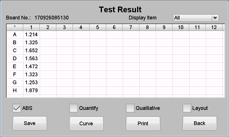
Figure 24
If the layout for the multi item layout, convenient for users to view data from the display, you can select the item to display from the display item drop-down list, unrelated items will be shielding.
Click "Layout" to check the condition of layout board.
Click "ABS" to view the absorbance value and click the single sample well position to modify the sample absorbance value.
Note: If the measured absorbance is > 4.000 A, it is shown as 4.00 *; < 0.000A will show as 0.00 *.
Click “Qualitative” to view the qualitative of the result according to the setting of the item.
Click “Quantify” to view the calculated value. In the Cut-Off item, the quantitative value is the value of S/CO. But in the quantitative item, the value is the calculated concentration.
Click “Save” to save all the values of the plate. The memory of the instrument can save more than two thousand plates. Save success will prompt "Save success!"
Click “Print” to print all the values by the position. The holes that not positioned will be neglected automatically.
Click “ Back ” to layout interface.
9. Sample Information
Click the “Sample Info” icon in the main menu to enter the setting of the sample information.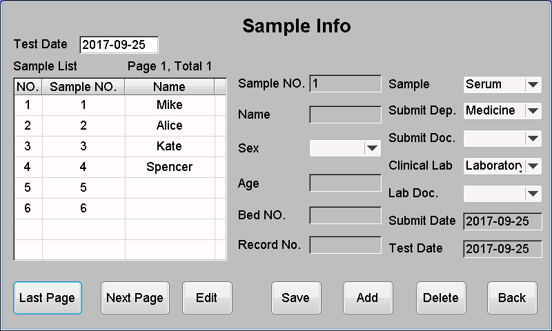
Figure 25
9.1 Basic operation
Includes adding, modifying, and deleting patient information.Operation procedure:
First of all, enter the test date, the form will list the sample no. and patient name for the specified date be based on patient information and samples of the test.
Click the “Add” button to add a new patient message;
Select a patient item and click the “Modify” button to modify a new patient message;
Select a patient item and click the “Delete” button to delete patient information from the selected patient.
Click the “ Last Page” & “ Next Page ” to display the patient information on the last page or next page.
Note: If you add patient information, be sure to check the date of submit date and test date, otherwise there may be errors.
9.2 Sample(Patient) information
Click the “Add” , the patient information edit control, which allows the user to edit.Sample No. : When modifying patient information, you can modify the sample number, but need be careful this operation, so as not to cause errors;
Name: 6 bytes in length;
Sex: Male and female, default is blank;
Age: 0 - 150 years old, default 0 years old;
Bed No.: 9 bytes in length;
Medical record No: 9 bytes in length;
Sample type: Set in the dictionary function module, here only needs to select one item;
Submit department: Set in the dictionary function module, here only needs to select one item;
Submit doctor: Set in the dictionary function module, here only needs to select one item;
Inspection clinial lab: Set in the dictionary function module, here only needs to select one item;
Inspection lab doctor: Set in the dictionary function module, here only needs to select one item;
Submit date : Defaults to the same day, but the user can also modify;
Test date : When the patient's information is modified, the date of test may be modified, but the operation shall be carefully taken so as not to cause any error;
Which department type and inspection doctor is selected in the drop-down list, the list comes from the management information database, which operates in the dictionary function module.
After the patient information input is completed, press click “Save” to save the changes. Otherwise, it is considered to abandon modification.
10. Search
Click the ‘Search’ icon in the main menu to go into the menu of data searching.10.1 Sample(Patient) data searching
Press the “Sample Data” button, and then click “OK “ to enter the patient window. The patient form shows the test date, sample number, name, sex, and total number of all patients(count) eligible for the inquiry.
Figure 26
You can enter the send date , test date , name, sample number to search, search conditions is one of them.
For example: the send date is "2017-04-01", and all patients on 2017-04-01 can be searched.
For example, the sample number is 12, and all patients with a sample number of 12 can be searched.
● Select a patient item and click the “Sample report” button to enter the sample report window. View patient details at this window. Such as item name, result, unit / figurate and normal range of the item. Can also print, delete the sample report.
● Select a patient item and click “Patient information” button to enter the patient information window to view the patient's information.
● After select a patient item,the first column of the table will appear the words "P", click again can cancel it .Can click “ Select all ” , add "P" to multiple patient items, click “Print” can continuously print multiple patient report.
Click “Last page ” & “ Next page ” to view other patient information.
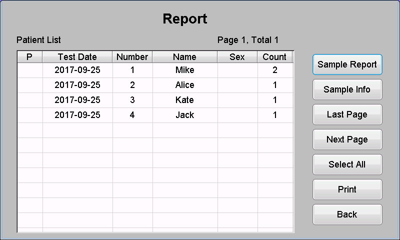
Figure 27
10.2 Item Report
Press the "Item report" button and click "ok" to enter the itemst test result search. Search according to Item name and Test date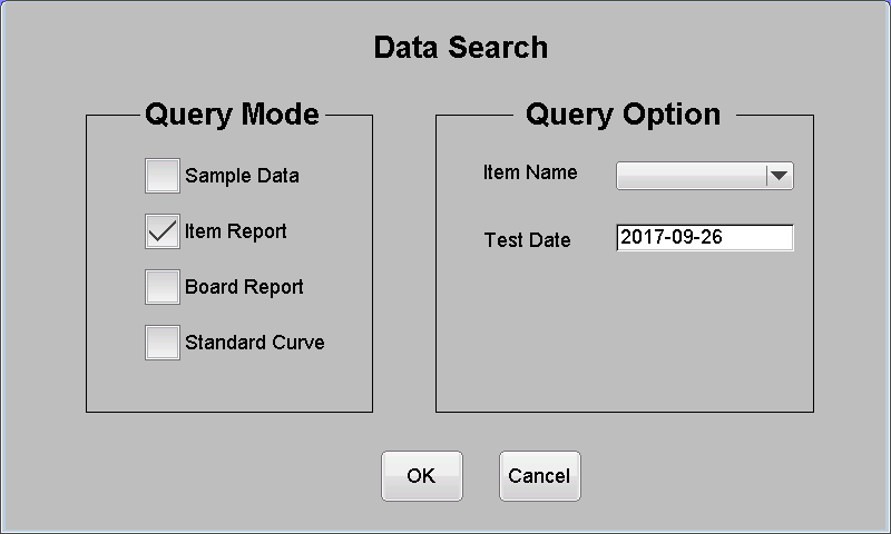
Figure 28
The item report window displays the patient's name, sample number, result, and figurate of all test results which is specified item and date. You can also click "Print" to print the item.
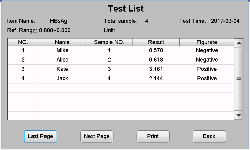
Figure 29
10.3 Board Report
Press the "Board report" button and click "ok" to enter the whole board test result search. Search according to Plate No. and Test date .
Figure 30
The contents of the board report are in accordance with the test results.
10.4 Standard Curve
Press the “Standard curve” button and then click the “OK ”button to enter the standard curve search. Search according to Item name .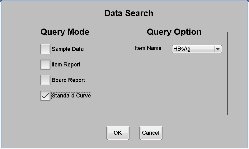
Figure 31
The Cut-Off item shows absorbance and formula values for each contrast sample.

Figure 32
The quantitative items show the concentration and absorbance of each standard sample and show curves simultaneously.
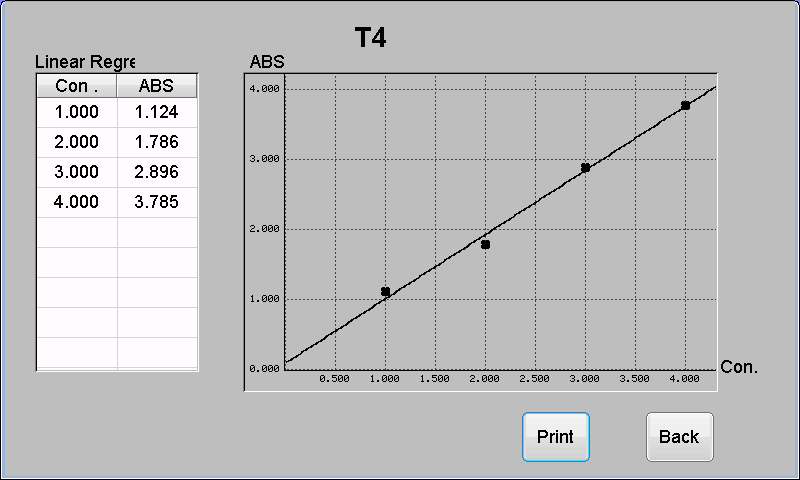
Figure 33
11. Report
In the main interface, press the "Report" button to enter the comprehensive report window. This button is a shortcut to check patient reports for the day.
Figure 34
12. PC Control
12.1 Software installation
The instrument can be controlled by the PC machine through the serial port, using PC interface software, more powerful, more convenient to connect to hospital management system, if using this method, the instrument must be set as follows: (the software instructions, please refer to the online help software)● Click on "System "
● According to the connection mode with PC, in the working mode select "PC mode RS 232" or "PC mode USB""
● Click "Save"
Note:If you need to install the software, please contact the agent or manufacturer. After setting to PC mode, the “Test” button on the main interface will be clicked invalid.
12.2 Software running environment
Operating system: Windows XP,7,8,10Hardware environment: Pentium III350 above, memory 128M, hard disk excess capacity of 500M or more, resolution 800*600 and above
Mode of communication: Serial communication, USB
Communication interface: RS232 serial port, USB
Baud rate: 19200
12.3 Software serial communication protocol and code
1)Frame format| Frame header | Serial number | Length | PDU type | Data | Check |
| One byte | One byte | Two bytes | Two bytes | N bytes | One byte |
Table 4
Frame header: The frame header is A5H, and the same bytes cannot appear in other fields in a frame; if another field appears A5H, then a A5H byte is added thereafter. When the receiver is in resolution, the receiver encounters a single A5H byte, which is considered as a synchronization header. It is considered to be a data byte when it encounters 2 consecutive A5H bytes.
Serial number: The back end is filled at will, but the front end must have the same serial number in the response frame
Length: PDU type field + total length of data field, NOT excluding synchronization head, serial number and check
PDU type: see the second part
Data: See the second part
Check: Single byte X OR check algorithm, range of calculation: serial number, length, PDU type, data
2) PDU type and data
0x0001 Front end reset
0x0002 Read front end version
0x0003 Front end version
0x0010 Command is complete without the need to return data
0x0011 Command is complete, but an error has occurred
0x0101 Vibrating plate
0x0102 Switching filter
0x0103 Measuring air blank
0x0104 Air blank AD value
0x0105 Moving plate
0x0106 Moving plate ABS value
0x0107 Got AD value of last moving
0x0108 Moving plate AD value
0x0109 Voltage settings (0 lightson, 1 lights off)
0x010A Gets the light on & off time
0x010B Light on & off time
0x010C Read the serial number (ID)
0x010D Serial number
0x0118 Long time vibrating plate
3)Instruction sending and answering
| Command | Data | Response | Data | Timeout time | Other instructions |
| Reset | 0x0010 | 15 seconds | |||
| Read front end version | 0x0003 | 4 bytes version number | 1 seconds | 2 bytes motherboard, 2 bytes from board, BCD code | |
| Vibration plate | 2 bytes (first byte vibration speed; second bytes vibration time) | 0x0010 | Vibration time +6 seconds | Vibration speed 1 slow, 2 medium, 3 fast Vibration time 1—60 | |
| Switching filters | 1 byte filter number (0—7) | 0x0010 | 10 seconds | ||
| Measuring air blank | No | 0x0104 | The 16 bit air AD value of 8 lines | 1 seconds | Data 16 bytes |
| Moving plate test | 1 byte vibration mode (0:continuous 1: stepping)△ | 0x0106 | 192 bytes, the 16 bit absorbance value of 96 wells | Continuous:10 seconds Stepping:30 seconds | Data 192 bytes,all values have been expanded by 1000 times 10005 means that the absorbance is too large 10006 means that the absorbance is too small |
| Moving plate AD values | 0x0108 | 208 bytes, the 16 bit AD value of 96 wells + the 16 bit air AD value of 8 lines | 1 seconds | Need to perform Moving plate test Instructions | |
| Switching voltage | 1 byte voltage stall (0 or 1) | 0x0010 | 1 seconds | ||
| Light on & off time | 0x010B | 1 byte voltage status, 2 bytes of time | 1 seconds | ||
| Read the unique identification number of the SN machine | 0x010D | 9 bytes SN | 1 seconds | ||
| Long time vibrating plate | 3 bytes (first byte vibration speed; second &third bytes vibration time) | 0x0010 | Vibration time +6 seconds | Vibration speed 1 slow, 2 medium, 3 fast Vibration time 1—60 |
Table 5
4)Error code
0x1201 Invalid filter number, valid: 0-7
0x1202 Invalid vibration plate time valid: 1-60s
0x1203 Invalid vibration plate speed, valid: 1-3
0x1204 Invalid moving plate mode, valid: 0、1
0x1205 Filter has no reset signal
0x1206 Elisa plate has no reset signal
0x1207 The elisa plate does not move or no positioning slot optical coupling signal 0x1208 AD does not have an OK signal
0x1209 Invalid voltage value ,valid: 0-1
0x120F Light source is too strong
0x1210 Light source is too weak
13. Shut down
Back to the system's main interface, you can turn off the power supply directly.14. Instrument maintenance
14.1 Summary
Microplate reader is a precision clinical analytical instrument. To make the instrument keep a good status, user must do routine maintenance well. Although maintenance of microplate reader is easy, user needs do it carefully.14.2 Cleaning instrument
● Keep working condition of the instrument clean.● User may use neutral clean solution and wet cloth to clean the instrument surface.
● User should clean LCD with soft cloth.
Note: Keep instrument away from dissolvent, oil and corrosive substance.
14.3 Instrument parts replacement
14.3.1 Replace fuses
1) Shut down power switch.2) Fuses are equipped in fuse box which is back of instrument power switch. Users pull box lid and replace fuses with same specification ones.
Fuse specification: F2AL 250V
3) Close the fuse box cover and restart the instrument.
Note: Users must use fuses of the above specification.
14.3.2 Replace halogen tungsten lamp
When halogen tungsten lamp is broken, replacement steps are as followings:1) Shut down instrument and open instrument upper cover.
2) Unscrew the visor fixing screws and take off the light visor.
3) Unscrew the screw of the top spring retainer of which is fixed the lamp, remove the cushion, remove the bulb, then pull the bulb from the lamp socket .
4) Install the new lamp and lamp socket (lamp type: OSRAM 64607, 8V/50W), reset the new lamp and fix the spring cushion.
5) Return light visor and tighten screws.
6) Return upper cover and restart the instrument.
Note: The lamp must be purchased with the specified brand and model.
14.4 Simple fault handling
| Phenomenon or hints | Reason analysis | Method | |
| 1 | Bulb not lighting | Bulb power supply abnormal Bulb broken | Check whether supply voltage is 8V Replace bulb |
| 2 | Plate holder no resetting signal | Plate holder position is too on the right side | Push it to the left 1 cm gently |
| 3 | Built-in printer unable to start | Printer power is not normal The press handle of built-in printer is not pressed | Check whether printer power voltage is 5 V Check whether the press handle of built-in printer is pressed |
| 4 | Built-in printer unable to print | Whether setting printer type Whether printer cable is connected well | The printer type in the System Settings is set to built-in printer or not Printer 10 core cable is connected well or not |
| 5 | Instruments sometimes appear messy code | Data storage uninitialized | Click all clear in Data query |
| 6 | LCD screen brightness is not enough | Display contrast whether adjusted | Click on system settings to adjust the contrast size |
| 7 | Filter wheel no reset signal | Connection of the control line is not good Optical fiber head not fixed Photoelectric coupler fault | Check whether the 7 core signal control line on the motor driver board is connected well Check whether optical fiber head is loose Turn the filter wheel, observe whether RT1 light emitting diode on Data Acquisition Board is change from dark to bright, if there is no change, change Filter Wheel Positioning Detection Plate |
| 8 | Instruments unable to start | Power supply is not normal Switch machine time interval is too short The motherboard does not start | Check whether instrument is electrified Check whether the power plug is loose Check the fuse Check the voltage Shutdown after waiting more than 30s to restart Motherboard failure, contact distributor or manufacturers to change the motherboard |
| 9 | External printer error | External printer connect later | System setup>Set Printer |
| 10 | Plate holder don’t move | Drive motor fault Plate holder reset error | Open the machine cover, check if the drive motor is rotating On the data board, Holzer components can not connect the magnetic steel of the plate holder |
| 11 | External printer unable to start | Printer power is not normal | Check if power plug is loose Check ON/OFF button |
| 12 | External printer unable to print | Printer setting is not correct | Check if printer type is setting correct Check if print cable is normal connection If printer is setting normal |
| 13 | External printer appears to fade, print quality decline | Printer problem | Replace the cartridge or ribbon, clean the print head (see the printer user's manual) |
| 14 | External printer paper jam and other faults | Printer problem | (See the printer user's manual) |
| 15 | Plate holder positioning detection signal abnormal | Plate holder transverse position is not normal | Check whether plate holder transverse plate is falling off, shifting Check whether 12 positioning grooves on the transverse plate is blocked Check plate holder positioning detection slot coupler |
| 16 | Xxx wavelength air gap is too low | Bulb broken Filter broken | Replace bulb Replace filter |
| 17 | Xxx wavelength air gap is too high | Filter not properly installed Filter broken | Check filter and filter wheel are properly installed Replace corresponding filter |
| 18 | Front end data acquisition board is not responding | The serial line between front board and data acquisition board is loose USB communication cannot identify USB signals | Reconnection 3 core serial line Reinstall the software's built-in USB drive |
| 19 | Plate moving test error | Not detected the plate holder reset signal(Not necessarily signal error, it is possible that the distance is too long) (The error is related to the position of the reset signal and slot coupler ) | Check the plate holder motion stroke length and force condition Check the position of slot coupler |
| 20 | Plate moving test data error | In the Cut - Off formula,calculated CO value is 0; Or in the quantitative formula, a standard ABS value exceeds the range of 0.000-4.000; Or in the quantitative formula, unable to get the curve after calculation, for example two different concentrations of standard ABS values are the same. | Check project setup and elisa plate layout situation |
| 21 | Standard concentration must be increasing | The concentration values of multiple standard must be increasing in the project setup | Read the reagent user manual carefully and understand the interpretation of the specification for standard solubility |
| 22 | Standard layout error | The quantity of standard wells does not match with the quantity of standard which is setted in the project in the number of items set in the standard quantity | Carefully verify the number of standard items in the reagent user manual |
| 23 | Contrast plate arrangement error | New projects do the plate moving for the first time,projects require setting contrast but layout do not not set (If the project require there are negative contrast and positive contrast at the same time , layout must do both) | It is recommended that the client set a negative and positive contrast well every time when they do the experiment |
| 24 | Negative control absorbance too low | Negative control value<0 | Confirm that there is no blank participation calculation under the double wavelength |
| 25 | Negative control absorbance too high | Negative control value>4.0 | Check if foreign objects are stained with lenses, if the experiment fails,the solubility of the sample is too deep |
| 26 | Positive control absorbance too low | Positive control value<0 | Confirm that under the dual wavelength there is not blank to participate in the calculation |
| 27 | Positive control absorbance too high | Positive control value>4.0 | Check if foreign objects are stained with lenses, if the experiment fails,the solubility of the sample is too deep |
| 28 | Cut-Off value error | Cut-Off value ≤0 | Check if the qualitative formula is wrong |
| 29 | Standard absorbance too low | Standard absorbance ≤0 | Confirm that there is no blank participation calculation under the double wavelength |
| 30 | Standard absorbance too high | Standard absorbance ≥4.0 | Check if foreign objects are stained with lenses, if the experiment fails,the solubility of the sample is too deep |
| 31 | Standard value error | Standard absorbance incorrect such as same absorbance value of standard with different concentration | Whether the test failed, whether the washing plate and adding sample is correct and whether there is cross contamination |
Table 6
Note: In the use of the process if users can not solve the error, or a mistake is repeated,please contact the seller.