


Ion Chromatography BCHR-102
- Sea, Air, Door to Door Shipping
- 1 Year Warranty
- US & European Standards
Chromatography is a technique that enables the separation, identification, and purification of the components of a mixture for qualitative and quantitative analysis. Our extensive range offers variety of products like Gas, Ion and Portable Ion chromatography products to meet all separation needs, including improved resolution, enhanced sensitivity, faster analysis and consistent performance.
- Temperature-control bipolar conductivity detector:
- Greater detection range, better precise analysis.
- Built-in circulating 3D constant temperature technology:
- Temperature stability time is less than 30 mins, ensuring the accuracy and reliability of test data.
Specification
Features
Applications
| Ion Chromatographic Pump: | |
| Maximum Pressure | 35 Mpa (PEEK) |
| Type | High-pressure and low-pulse two-piston tandem advection pump |
| Pressure Display Accuracy | ≤ 0.1 MPa |
| Flow Range | 0.001 ~ 9.999 mL/min |
| Pressure Pulse | ≤ 0.5% |
| Flow Stability | (0.2-0.5) mL/min ≤ 3%; (0.5-1.0) mL/min ≤ 2%; > 1.0 mL/min ≤ 2% |
| Allowable Deviation of Flow | (0.2-0.5) mL/min ±5%; (0.5-1.0) mL/min ±3%; > 1.0 mL/min ±2% |
| Numerical-control and Electromagnetic Sample Injector: | |
| Maximum Pressure | 35 Mpa |
| Contact Material of the Rotor | PEEK |
| Control Mode | By Stepper motor |
| Power Supply | 24 V (DC) |
| Conduction Detection System: | |
| Type | Temperature control and bipolar conductivity detector |
| Cell Volume | ≤0.8μL |
| Detection Mode | Bipolar conductivity detection |
| Detection Range | 0~45000 μS/cm |
| Detection Resolution | ≤0.0020nS/cm |
| Output Voltage | -6000~+6000 mv (adjustable) |
| Electronic Noise | 0.02 nS |
| Baseline Noise | ≤ 0.001 μS/cm |
| Baseline Drift | ≤ 0.02μS |
| Operating Temperature Range | Room temperature +5°C~60°C |
| Controlling Temperature Accuracy | ±0.01°C |
| Maximum Pressure | 10.0 Mpa |
| Linear Range | ≥ 10 3 |
| Instrument Linearity | ≥0.999 |
| Quantitative Repeatability | ≤1.0% |
| Qualitative Repeatability | ≤0.1% |
| Minimum Detectable Concentration | Cl- ≤ 0.0005 ug/mL; Li+ ≤ 0.001 ug/mL; BrO3≤ 0.001 ug/mL |
| Flow System: | |
| Six-way Valve | PEEK material, pressure 5000 psi; Independent automatic collecting and flow function. |
| Suppressor: | |
| Type | Self-Regenerating electrolytic micro-membrane suppressor |
| Maximum Pressure | 6.0 Mpa |
| Dead Volume | <50 μL |
| Other Specifications: | |
| Dimension (LxWxH) | 350x470x510 mm |
| Net Weight | 26 kg |
| Gross Weight | 32 kg |
| Power | 150 W |
- Temperature-control bipolar conductivity detector:
- Greater detection range, better precise analysis.
- Built-in circulating 3D constant temperature technology:
- Temperature stability time is less than 30 mins, ensuring the accuracy and reliability of test data.
- The world's leading full-range series of ion chromatographic columns:
- High efficiency, large capacity of the columns for detecting ions of varied
- compositions.
- Self-Regenerating Electrolytic Micro-membrane Suppressor:
- High pressure resistance, small dead volume, highly responsive to signals.
- Able to detect anions and cations at the ppb level.
- Work across a variety of detectors, to expand the scope of applications of ion chromatography.
Food Testing, Chemical Industry, Beverage Testing, Drug testing, Forensic Science, Pharmaceutical, Molecular Biology, Medical, Research, Laboratory
Operating Manual for BCHR-102
Introduction
Safety Precautions
Specific cautions:
Safety signs
1. Instrument Introduction
1.1 Front panel of the instrument
1.2 Top cover of the instrument
1.3 Component panel of the instrument
1.4 Rear panel of the instrument
2. Instrument Components
2.1 Infusion pump
2.2 Electromagnetic injection valve
2.3 Column heater
2.4 Conductivity detector
2.5 Ampere detector (optional)
2.6 Suppressor
2.7 Eluent generator (optional)
2.8 Schematic diagram of system flow path
2.9 Sample loop specification
3. Instrument Operation and Maintenance
3.1 Start-up
3.2 Water quality requirements
3.3 Checking all connections
3.4 Balance system
3.5 Preparation of samples
3.6 Injection and analysis of samples
3.7 Maintenance
4. Troubleshooting
4.1 Pump pressure fluctuation
4.2 Frequent overpressure
4.3 Large baseline noise
4.4 Large baseline drift
4.5 Too high background value
4.6 Low response value
4.7 Abnormal suppressor current
4.8 No peak
4.9 Peak tailing
4.10 Poor degree of separation
4.11 Poor repeatability
4.12 Poor linearity
4.13 There are bubbles in infusion pump
4.14 Handling of abnormal instrument control
5. Maintenance
5.1 Removal of blocking units
5.2 Replacement of pipelines and joints
5.3 Replacement and cleaning of the check valve
5.4 Replacement of sealing ring or plunger rod
5.5 Replacement of conductivity cell
5.6 Replacement of amperometric detection cell gasket
5.7 Replacement Reference Electrode
5.8 Replacement of the suppressor
5.9 Replacement of the power fuse
5.10 Replacement of the eluent generator storage tank
5.11 Replacement of trap column
A. Norms
A.1 Electrical correlation
A.2 Physical correlation
A.3
A.4 Pump
A.5 Conductivity detector
A.6 Conductivity cell
A.7 Valve
A.8 Column heater
B. Installation
B.1 Equipment requirements
B.2 Unpacking
B.3 Installation software
B.4 Connecting the instrument to computer
B.5 Connecting the autosampler to the instrument (optional)
B.6 Connecting power cord
B.7 Installation of chromatograph column and suppressor
B.8 Connecting waste liquid pipes
B.9 Installation of eluent bottle
B.10 Flushing pump
B.11 System balance
B.12 Confirmation of operation status
B.13 Pressurization of eluent bottle (optional)
Introduction
Thank you for choosing our BCHR-102 Ion Chromatograph. We will wholeheartedly provide you with high-quality service.BCHR-102 Ion Chromatograph adopts bipolar constant temperature conductivity detector, which can give consideration to the detection of various ions with concentrations different by four orders of magnitude in the analysis sample. The separation and detection can be carried out at the same time by one injection, with fast analysis speed and high sensitivity. There is no need to manually switch different measuring ranges and dilute for multiple times, thus greatly reducing manual operation and the errors caused thereby.
BCHR-102 Ion Chromatograph can not only provide users with a complete set of solutions for conventional inorganic anion and cation in drinking water, disinfection by-products and additives, bromate, organic acid and amine in food, but also easily measure samples containing both minor components and high-content components such as dialysate and eye washing liquid. In many other fields, BCHR-102 Ion Chromatograph can also provide complete application support and extensive and practical application supporting schemes.
The BCHR-102 Ion Chromatograph not only features extensive, perfect and advanced application and solution capabilities, but also brings users an automatic, humanized and interesting instrument application experience by combining with automatic control mode and the upgrade to automatic sampling system at any time.
To facilitate users to get familiar with the operation and simple daily maintenance of the product as soon as possible, the User Manual is specially provided. It is a necessary document for the instrument and is recommended to be placed beside the instrument for the staff's reference at any time. To use this instrument better, please read this manual carefully. This manual will introduce the details of components and operation of the instrument as well as the maintenance of common faults and the replacement of instrument accessories, etc.
Safety Precautions
BCHR-102 Ion Chromatograph is specially designed for the application of ion chromatography and should not be used for other purposes. If accidents or losses are caused due to users' use of the equipment in other aspects, the Company will not assume any responsibility.This manual contains precautionary instructions and warnings during instrument operation. Please observe them consciously. Security messages are shown in bold and accompanied by icons, as shown below.
 : remind you of the environment that may affect the instrument but will not cause personal injury.
 : remind you of dangerous environment that may cause serious damage to the instrument or endanger personal safety.
 : remind you of dangerous environment that may cause immediate death or serious injury.
 : Due to the large power supply current used by this instrument, personal injury such as electric shock may be caused. When handling the instrument, please turn off the power supply of the instrument and unplug the power cord first. It is forbidden
to move the protective casing of live equipment such as instruments or circuit boards.
Specific cautions:
1. Precautions for electric related operation
The power cord is used as the main device to cut off the power supply ofthe instrument. Ensure that the socket is located near the instrument and easy to insert.
Please pay attention to grounding.See section 1.3.
To avoid electric shock, please use the socket with grounding. Do notoperate the instrument without grounding. See section B.6.
The power supply current used by this instrument is large, which may cause personal injury such as electric shock. Therefore, please turn off the power supply and unplug the power cord before handling. When handling the instrument, please fasten the casing of theinstrument. It is forbidden to move the protective casing of live equipment such as circuit boards. See section B.2.
Before plugging and unplugging the conductivity cell, please turn off the heating button of the conductivity cell and the power switch of the instrument to avoid the damage to the circuit board. See section 2.4. The suppressor cable should be connected properly, otherwise no current will be applied. See section 5.8. Do not replace the fuse at will. If you cannot confirm the fuse type, please contact the instrument manufacturer. See section 5.9.2. Handling Precautions
:Because the instrument is heavy, it should be handled by two or more persons. During handling, lift the bases on the left and right sides of the instrument. It is forbidden to lift the front and back sides, otherwise the soundness of the front door will be damaged. See section B.2. :The instrument is forbidden to contact sharp objects to avoid scratching of the surface coating. See section B.2.3. Precautions for the use of eluent generator
:The liquid storage tank is filled with high-concentration KOH or MSA solution which is extremely corrosive. Please do not disassemble the tank by yourself to prevent injury accidents. See section 2.7. : Please make sure the system pressure is within the applicable range (≤17MPa) before using the eluent generator to avoid damaging the equipment. See section 2.7. :Before using the eluent generator, first start the infusion pump and flush the pipeline with pure water for 5 minutes. Then open the exhaust valve, set the concentration value and power on; after using this instrument, close the exhaust valve, power off, and flush the pipeline with pure water for at least 10min. See section 2.7. :the concentration range of the eluent generator is 0 mmol/L to 100 mmol/L. Please do not enter a value greater than 100 in the "Concentration" column. See section 2.7. :KOH or MSA solution with strong corrosivity is filled in the eluent generation tank. Please wear rubber gloves and goggles during operation to prevent burns. See section 5.10.4. Precautions for experimental operation
:Injection signal is responded only when sampling is started. See section 2.2. :The experimental operators should conduct the experiment strictly in accordance with the laboratory operation specifications. Protective equipment such as goggles and laboratory gloves should be worn during the pretreatment operation to avoid personnel injury caused by improper operation. See section 3.5. : When using aqueous solution as eluent, bacteria are easily generated, thus affecting the experiment. The contaminated filter head should be cleaned or replaced in time. See section 3.7. : To avoid impurities in the pipeline in the new conductivity cell, ultrapure water should be used for flushing for about 12h before replacing the new conductivity cell. See section 5. 5. : When using ampere detector, please wear dust-free gloves to operate to avoid polluting the electrodes. See section 5.6. :When installing the chromatograph column, the pump flow rate should be reduced to 0.3 mL/min or less. When the new chromatograph column is connected to the chromatograph system for the first time, first flush with water and eluent and disconnect the conductivity cell and suppressor to prevent high conductivity substances or bubbles from entering the conductivity cell or suppressor. When clean and bubble-free liquid flows out of the outlet of the chromatograph column, connect the conductivity cell and suppressor. See section B.7. :To prevent siphoning of waste liquid, please check whether the waste liquid pipe is bent, squeezed or raised at any time. See section B.8. :Waste liquid bottles should not be sealed. During the operation of the instrument, the continuous self-regeneration suppressor uses electrolysis to suppress the background, and a small amount of oxygen and hydrogen will be generated during electrolysis. Gas should be prevented from staying in the waste liquid bottle so as not to generate static electricity. In serious cases, there may be explosion. See section B.8. :When the instrument is used for the first time or for a long time, or when it is not normally used, the pump head should be rinsed clean to prevent residual crystals in the pump head from damaging the pump head. See section B.10. :When replacing the plunger rod, please insert and withdraw the plunger rod vertically. Any lateral movement will cause the plunger rod to break. See section 5.4.Safety signs
The following safety signs appear on the labels of the cabinet or components of BCHR-102 Ion Chromatograph.~AC
 Grounding
丨 Power on
 Power off
Deionized Water Requirements for IC
| Technical indicators | |
| Resistivity | ≥18.25 MΩ·cm |
| TOC | <10 ppb |
| Metal ion | <1 ppb |
| Pyrogens | <0.03 Eu/mL |
| Particulate matter (> 0.2μm) | <1 unit/mL |
| Silica gel | <10 ppb |
| Bacteria | <1 cfu/mL |
Table 1
1. Instrument Introduction
1.1 Front panel of the instrument
The front panel of BCHR-102 Ion Chromatograph is shown in Figure 1-1.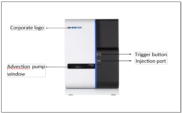
Figure 1-1
Front panel of the instrument
Injection port
The sample to be analyzed manually is injected into the sample loop through the injection port with a syringe. If you want an autosampler, you must connect the autosampler. For more information about autosampler, see section 3.6.2.
Trigger button
After the sample is injected into the loop, press the trigger button manually, and the instrument will trigger the software to collect the chromatogram.
1.2 Top cover of the instrument
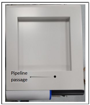
Figure 1-2
Diagram of the top cover of the instrument
1.3 Component panel of the instrument
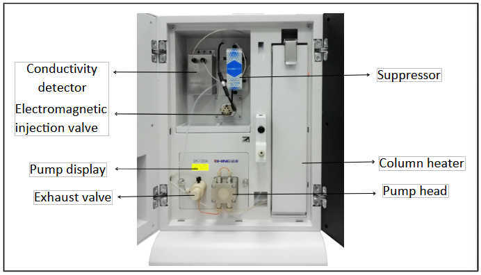
Figure 1-3
Instrument component
Pump display
The pump display shows the pressure and flow rate when the system is running.
Pressure sensor
The pressure sensor is located at the rear end of the exhaust valve and senses the pressure of the flow path system. The value can be read from the pump display screen.
Pump head
BCHR-102 adopts double-plunger high hydraulic infusion pump. The flow rate can be set at
0.001 mL/min to 9.999 mL/min. However, to achieve optimal performance, the general flow rate is set at 0.200 mL/min to 2.000 mL/min. The infusion pump has high and low pressure protection function. Please refer to section 2.1 for more information about the pump.
Electromagnetic sampling valve
Electromagnetic sample injection valve is PEEK material high voltage electromagnetic automatic six way valve. See section 2.2 for details.
Column heater
It is used to heat the guard column and chromatograph column, the temperature can be adjusted above ambient +5℃ to 60℃. The specific setting temperature is subject to the operating temperature of the chromatograph column you have configured. The heater has built-in eluent preheating module. The eluent entering the chromatograph column is preheated to reduce thermal shock and thus improve the thermostatic effect in the chromatograph column.
Conductivity detector
The conductivity detector detects the conductivity of ions flowing through the cell body. BCHR-102 Ion Chromatograph is equipped with thermostatic bipolar conductivity detector. The tank body contains a heat exchanger, and the temperature of the detector can be adjusted within the range of 5℃ to 60℃ .Please refer to section 2.4 for details.
Suppressor
The suppressor can reduce the background conductance of eluent and improve the signal value of ions to be detected, thus obtaining ideal detection results. Please refer to section 2.6
1.4 Rear panel of the instrument
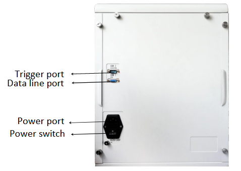
Figure 1-4
Rear panel of the instrument
Trigger port
The trigger port connects the instrument with the autosampler through a trigger line which triggers the working software to start sampling.If you use ShineLab software, no need to connect this port.When using Shine software, you need to connect.
Data line port
The data line port connects the instrument with the computer through the data line, and outputs the signal detected by the ion chromatograph to the working software.
Power cord port
One end of the power cord is connected to the instrument and the other end is plugged into an AC power outlet.
:This power cord is used as the main device to cut off the power supply of the instrument. Ensure that the socket is located near the instrument and easy to insert. Please pay attention to grounding.Power switch
The power switch provides switch control of the instrument power supply.
2. Instrument Components
2.1 Infusion pump
The Pump equipped for this instrument is an intelligent high-pressure constant-current infusion pump with a built-in micro flow pressure sensor to monitor the flow in real time. it has intelligent pressure limiting function to effectively guard columns. it is matched with the latest pulse decrement technology, providing high stability and low pulsation to meet various applications of ion chromatography. it has a chemically inert non-metallic undamped pump head connecting to a full PEEK pipeline. It is suitable for eluent with a pH of 0 to 14 and reverse-phase organic solvent. it has high stability and repeatability. its built-in chip can adjust the flow stability according to the pressure change. It has the functions of over-pressure automatic alarm, self-stop of pump and self-protection. The pressure setting can be performed on the software.2.1.1 Pressure sensor
The pump head conveys the eluent through a pressure sensor which detects the pressure of the system flow path in real time. Observe whether the system pressure is stable and accurate through the value displayed on the pump screen. The system pressure should be kept consistent (the difference between early reading and later reading should be less than 0.5MPa).2.1.2 Exhaust valve
When the system needs to exhaust( (there are bubbles or empty pipes), turn the exhaust valve counterclockwise for 1 turn to open the exhaust valve. After the exhaust valve is opened, the eluent in the flow path will flow here and be discharged. When the gas entering the pump is to be exhausted, the exhaust valve can be opened. Use the exhaust needle tube to extract the gas. After the exhaust, tighten the exhaust valve clockwise.2.2 Electromagnetic injection valve
Electromagnetic injection valve is PEEK material high-voltage electromagnetic automatic six-way valve, withstand 35MPa. With the function of automatic signal acquisition and uninterruptible flow; It has the characteristics of acid and alkali resistance, corrosion resistance, wear resistance, fatigue resistance and 100% organic solvent resistance.Electromagnetic injection valve has two positions: Load and Inject. During sample loading, the eluent flows through the solenoid valve through the chromatograph column without passing through the sample loop, and the samples are injected into the sample loop and stored until analyzed, and the excess samples are emptied from the waste liquid tube. During analysis, the eluent enters the sample loop and carries the sample into the chromatograph column for analysis.The specific circulation sequence is shown in Figure 2-1:
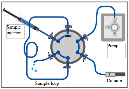
Load position
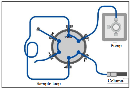
Inject position
Figure 2-1
Working principle of six-way valve
2.3 Column heater
The column heater provides a constant temperature environment for the Guard column and the chromatograph column, and the temperature can be adjusted above ambient +5℃ to 60℃. The optimal setting temperature should be 5℃ above room temperature or subject to the column specification selected. A pre-column eluent preheating module is contained in the column oven, so that the test sample can be heated uniformly before entering the column, thereby reducing peak diffusion and peak broadening, improving the separation degree and making the peak shape symmetrical.2.4 Conductivity detector
The conductivity detector can quantitatively detect the target ions separated by the chromatograph column. BCHR-102 Ion Chromatograph is equipped with constant temperature bipolar conductivity cell. The cell body contains a heat exchanger, and the temperature of the conductivity cell can be adjusted in the range of 5℃ to 60℃. The optimal setting temperature should be 5℃ above room temperature or subject to column report.Advantages of constant temperature bipolar conductivity cell:
(1) Excellent precision and linearity, wide working range;
(2) Small dead volume and extremely low diffusion;
(3) The interference of electrode polarization and electric double layer is well eliminated, and the influence of electrode pollution on sensitivity is reduced.
(4) In the conductivity detection system, the suppressor effectively reduces the background conductivity value of the eluent, and the constant temperature of the conductivity cell further reduces the influence of temperature on conductivity and improves the stability of the baseline.
:Please turn off the heating button of the conductivity cell and the power switch of the instrument before plugging and unplugging the conductivity cell to avoid the damage to the circuit board.2.5 Ampere detector (optional)
Ampere detectors are commonly used to analyze ions which are difficult to detect with conductivity detectors and have electrical activity and low dissociation degree. Ampere detector is shown in Figure 2-2.
Figure 2-2
Appearance of DC ampere detector (SHE-3)
Ampere detector consists of potentiostat and detection cell.
The amperometric cell is a three-electrode volt-amperometric detection cell consisting of a titanium counter electrode, a working electrode and a reference electrode. Thin-layer flow design is adopted so that the smooth electrode surface can reduce flow noise.
According to the analysis, Au, Ag, Pt and GC electrodes can be selected as working electrodes which are respectively suitable for analysis of different substances.
The reference electrode usually uses Ag/AgCl or saturated calomel electrode.
The counter electrode is made of gold, platinum, glassy carbon, titanium, stainless steel,
etc.
The reference electrode and the counter electrode should be placed downstream of the working electrode to prevent the leak of reaction products of the electrode and the reference electrode from interfering with the working electrode.
The electrochemical detector supports three operating modes according to different applied potentials: direct current ampere (DC), integral ampere (including pulse ampere) and cyclic voltammetry.
D.C. ampere detection: D.C. ampere detection is to continuously apply potential to the working electrode.
Integral and pulsed amperometric detection: integral and pulsed amperometric detection is to apply a series of continuously changing potentials in one cycle and is repeated, so that the electrode surface can be continuously regenerated.
Cyclic voltammetric amperometric detection: this method controls the potential to scan repeatedly at different rates and with triangular waveform for one or more times over time, resulting in redox reaction on the surface of the working electrode.
2.6 Suppressor
The suppressor can reduce the background conductance of eluent and improve the signal value of ions to be tested, thus improving the testing capability of ion chromatograph. The operation principle of suppressor is shown in Figure 2-3. After use, the residual inorganic salts in the suppressor should be flushed with ultrapure water for 10 min(1mL/min). Then, the four interfaces should be plugged with plugs. The suppressor should be sealed for preservation. Water infiltration should be conducted every one to two weeks, otherwise the suppressor will have high pressure inside or leak liquid.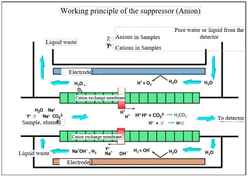
Figure 2-3
Schematic diagram of the suppressor’s working principle
2.7 Eluent generator (optional)
The eluent generator is a device that automatically generates eluent on line by using the principle of electrolyzed water. The device consists of eluent tank, electrolysis generating device, degassing device, circuit control and other parts. The eluent tank contains ultrapure water with resistivity not less than 18.25Ω·cm. When the device is used, only ultrapure water needs to be input at the end of the infusion pump, and no operator is required to prepare a eluent, which can reduce the abrasion of the plunger of the infusion pump by salt solution crystallization and effectively prolong the service life of the infusion pump.The specific working principle diagram is shown in Figure 2-5. The KOH eluent generator generates OH- eluent for anion exchange separation, and the MSA eluent generator generates methanesulfonic acid eluent for cation exchange separation. For more detailed information, please refer to the User Manual of the Eluent Generator.
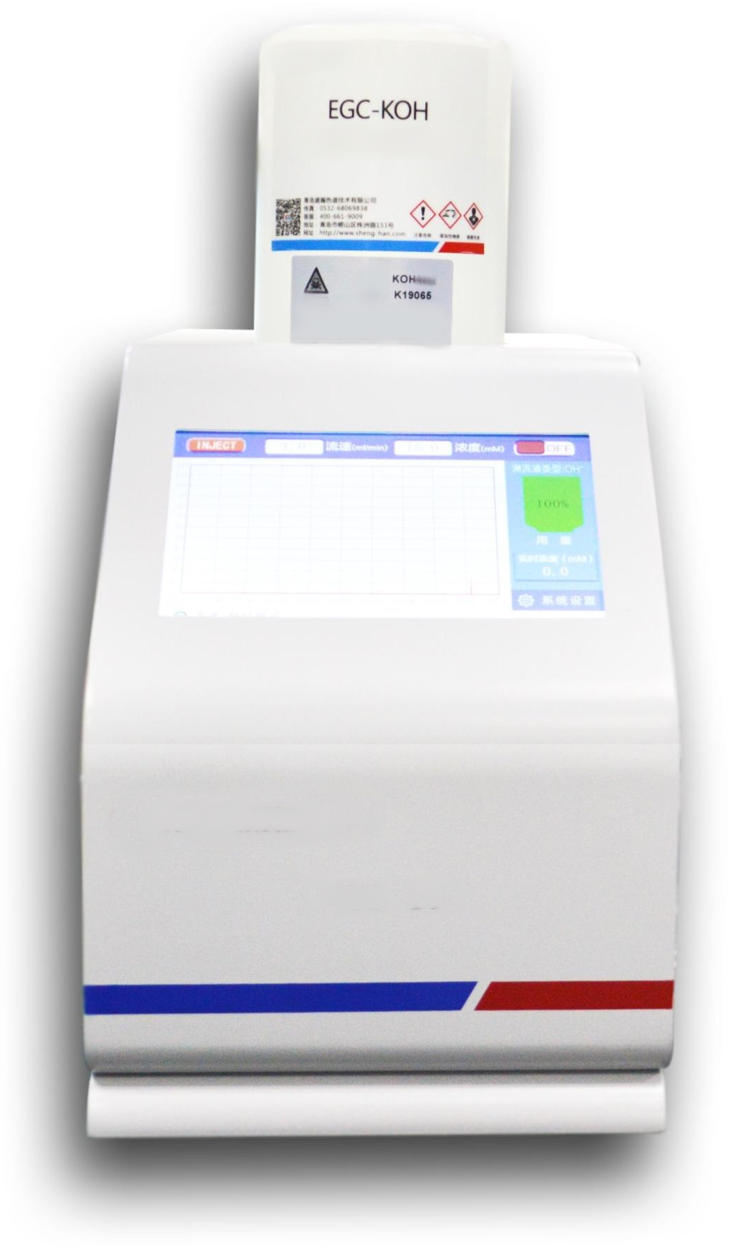
Figure 2-4
External view of eluent generator
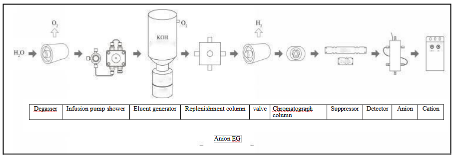
Figure 2-5
Schematic diagram of eluent generator
Flow path connection
One end of the eluent generation tank is connected with the ultrapure water output by the infusion pump, and the other end is connected with the ELUENT IN end of the trap column. The two interfaces can be connected at will regardless of sequence.
Exhaust port connection
During the transportation of the eluent generator, the plug is used to seal the exhaust port to prevent the solution from leaking. If the eluent generator is used for the first time, remove the plug of the exhaust port and connect the exhaust pipe with the on-off valve to the exhaust port at the bottom of the bottle. Open the valve (in the direction of the pipe) during use and close the valve (perpendicular to the pipe) after use. To effectively isolate carbon dioxide in the air during use, the outlet end needs to be sunk below the level of pure water.
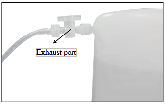
Figure 2-6
Schematic diagram of exhaust port
High pressure limit
The pressure resistance of the eluent generator is ≤17MPa. To ensure the long-term stable operation of the equipment, it is recommended that the daily working pressure is <15 MPa. If the system pressure is too high, please carefully check the cause of overpressure in the flow path and eliminate the problem in time to prevent damage to the device.
Low pressure limit
The device generates a large amount of gas during electrolysis. The gas needs to pass through the degassing membrane under a certain osmotic pressure for elimination. The recommended daily working pressure is >8MP.
Precautions
:the liquid storage tank is filled with high concentration KOH or MSA solutionwhich is extremely corrosive. Please do not disassemble by yourself to prevent injury accidents.
: please confirm whether the system pressure is within the applicable range (≤17MPa) before using this equipment to avoid damaging this equipment. :Before using the equipment, first start the infusion pump to flush the pipelinewith pure water for 5 minutes. Then, open the exhaust valve, set the concentration value and power on; after using this equipment, close the exhaust valve, power off and flush the pipeline with pure water for at least 10minutes.
: When transporting or moving the equipment, please check whether the exhaust port is sealed to prevent the internal solution from leaking. :The concentration range is 0 mmol/L to 100 mmol/L, please do not enter a value greater than 100 in the "Concentration" column.2.8 Schematic diagram of system flow path
Schematic diagram of chromatographic system flow path is shown in Figure 2-7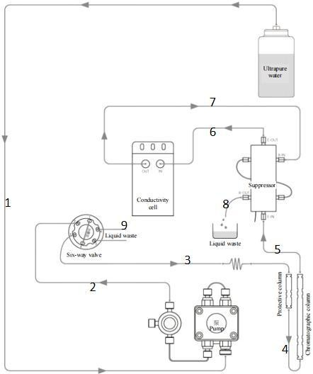
Figure 2-7
Schematic diagram of BCHR-102 flow path connection
Recommended pipeline and length
| Pipeline Name | Pipeline NO. | BCHR-102 |
| Eluent Bottle- Pump | 1 | 150FL |
| Pump - Valve 2 | 2 | 40 P1+200 P7 |
| Valve 3 - Guard Column | 3 | 80P2 |
| Valve 1- Valve 4 | None | Sample loop |
| Valve 6 - Waste Bottle | 9 | 100F7 |
| Guard column - Chromatograph Column * | 4 | 25P2 |
| Chromatograph Outlet - Suppressor IN* | 5 | 30P2 |
| Suppressor OUT - Conductivity Cell IN* | 6 | 22P2 |
| Conductivity Cell OUT - Suppressor RIN* | 7 | 28P7 |
| Suppressor ROUT - Waste Bottle | 8 | 100FL |
Table 2
ps:*Indicates that the pipeline needs to be cut by the user with a blade. SHA is an abbreviation for autosampler.
The number before the type is the length of the pipeline(For example,150FL=150cm Tetrafluoro Tube 1/8(3.175)*1.6).
| Pipeline | Pipeline Specification | Remark |
| FL | Tetrafluoro Tube 1/8(3.175)*1.6 | |
| P1 | PEEK Tube 1/16*0.13mm | |
| P2 | peek Tube 1/16*0.25mm | |
| P5 | peek Tube 1/16*0.50mm | |
| P7 | peek Tube 1/16*0.75mm | |
| F5 | Tetrafluoro Tube 1/8*0.5mm | |
| F7 | Tetrafluoro Tube 1/8*0.75mm | |
| F8 | Tetrafluoro Tube 1/8*0.80mm | It is only used as waste liquid tube, not buffer tube |
Table 3
Chromatograph system accessories include the following parts.
1. Guard column: adsorbing harmful components or particles in the sample or eluent to protect the chromatograph column.
2. Chromatograph column: separating sample components.
3. Self-regenerating suppressor: reducing the background conductivity of eluent; and improving the signal value of ions to be measured.
4. Constant temperature conductivity cell: detecting separated components. The specific chromatograph flow path system is described below.
The degassed eluent firstly enters the infusion pump and is conveyed by the infusion pump into the sample injection valve. When the sample is loaded into the quantitative loop, the sample injection valve is switched to the analysis state to bring the sample in the quantitative loop into the flow path. The mixed solution of the eluent and the sample enters the Guard column and chromatograph column in sequence after pre-column preheating in the column oven. After separation by the chromatograph column, it enters the suppressor and the conductivity cell. The conductivity cell will analyze the sample. The electrical signal is converted into a digital signal and transmitted to the computer end for analysis. After the liquid exits the conductivity cell, it will circulate into the suppressor to replenish the water in the suppressor regeneration chamber. Finally the waste liquid will enter the waste liquid bottle.
2.9 Sample loop specification
| Loop size (μL) | Internal diameter(PEEK) | Length (cm) |
| 50 | 0.75 | 11.3 |
| 100 | 0.75 | 22.6 |
| 200 | 0.75 | 45.3 |
| 250 | 0.75 | 56.6 |
| 500 | 0.75 | 113.2 |
| 25 | 0.5 | 12.7 |
Table 4
3. Instrument Operation and Maintenance
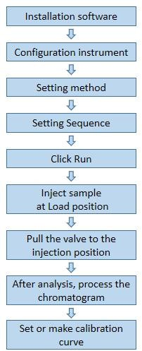
Figure 3-1
Software use process
3.1 Start-up
Turn on the power supply of BCHR-102 instrument, and the status of each component of the instrument is shown in Table 3-1. Start the reverse control software, fill the eluent bottle with eluent, and drain the bubbles in the infusion pump.Status of instrument components
| Pump | Closed |
| Valve | Loading |
| Conductivity cell | Closed |
| Suppressor | Closed |
| column oven | Closed |
Table 5
3.2 Water quality requirements
All kinds of solutions are prepared with ultra-pure water. The water should be distilled first and then treated by a purifier; or, the water may be exchanged by compound or mixed ion exchange resin bed; the double distilled water distilled by quartz still can also be used. The water resistivity should be above 18.25MΩ·cm.BCHR-102 Ion Chromatograph can be equipped with on-line degasser. After providing the degasser, moving phase does not need to be degassed and only needs to be prepared according to chromatograph column requirements. The moving phase is directly stored in mobile phase bottle and can be directly operated.
3.3 Checking all connections
Make sure that the eluent bottle is full of eluent; all pipe joints are tightly connected; suppressor cables are completely connected and the waste liquid pipe is in the waste liquid bottle.3.4 Balance system
When the system is balanced, check whether all parameters are normal.1. Whether the column pressure is normal (refer to the user manual of relevant chromatograph columns);
2. The system pressure fluctuation should be less than 0.5MPa;;
3. Whether the cell temperature of the conductivity cell and the column oven reach the set value and are relatively stable. The change range should be less than 0.4℃;
4. Whether the suppressor current is normal. The change range should be no more than 2mA.
5. Whether baseline noise and drift are normal. Parameters vary according to different eluent systems.
3.5 Preparation of samples
3.5.1 Selection and preservation of samples
Samples are collected in polytetrafluoroethylene bottles cleaned with ultra-pure water. Do not wash the container with strong acid or washing liquid to prevent a large amount of anions from remaining on the container and affecting the accuracy of analysis results.If the sample cannot be analyzed and used on the day of sampling, it should be immediately filtered with 0.22μm filter membrane, otherwise the bacteria in the sample may change the concentration of the sample with time. Even if the sample is stored at 4℃, the growth of bacteria can only be inhibited and cannot be eliminated.
Analyze NO2- and SO 2- samples as soon as possible. They will be oxidized to NO - and SO 2- ions respectively. Samples that do not contain NO2- and SO32- ions can be stored in refrigerator without significant changes in anion concentration within one week.
3.5.2 Sample Pretreatment
Cleaner samples such as acid rain, drinking water and filter liquor of atmospheric smoke can be directly injected for analysis. However, samples containing more other impurities, such as wastewater and surface water, need to be pretreated according to requirements before injection analysis. For samples with high concentration of impurities, the impurities should be filtered out through the pretreatment column in advance. We provide a variety of SPE cartridges for selection as required.Before pretreatment, samples should be separately connected to pretreatment columns (multiple pretreatment columns can be connected at the same time). Hold the pretreatment column with one hand and push the injector with another hand. If the push-in resistance of the sample is found to be too large, inspection should be carried out to avoid violent injection.
: The experimental operators should conduct the experiment strictly in accordance with the laboratory operation specifications. Protective equipment such as goggles and laboratory gloves should be worn during the pretreatment operation to avoid personnel injury caused by improper operation.3.5.3 Dilution of samples
The concentration of ions in different samples will vary greatly, thus no certain dilution factor cannot be given. In most cases, low concentration samples can be injected without dilution.If Na2CO3/NaHCO3 is used as eluent, sample dilution with them can effectively reduce the influence of negative peak of water on F- and Cl- (especially when the F- concentration is less than 50ppb). However, blank and standard solutions should be prepared with eluent at the same time. The specific method is to add 1 mL of 100-fold concentrated eluent to 100 mL of sample.
3.6 Injection and analysis of samples
BCHR-102 supports two injection modes, manual injection and automatic injection.When using an autosampler for injection, disconnect the instrument from its own injection valve line, connect the autosampler injection valve from the pump, and then enter the Guard column. The mode of connection with the instrument varies from different types of autosampler. Please refer to section B.5 for specific connection mode.
3.6.1 Manual injection
1. Ensure that the injection port is connected completely.2. After the baseline is balanced, clean the injection port with ultrapure water first, and then fill the injector in the accessory box with the sample and inject it into the quantitative loop with a 0.22 μm needle filter. The injection volume should be slightly larger than the volume of the quantitative loop to ensure that the quantitative loop is filled with the sample. The excess sample will be discharged through the waste liquid pipe.
3. Leave the injector at the injection port end;
4. The software can be started to collect data by click the Trigger button ( START botton).
3.6.2 Autosampler injection
1. Confirm that the autosampler is fully connected with the instrument. Please refer to section B.5 for details.2. Load the test sample into the sample bottle and put the sample bottle into the sample tray of the autosampler;
3. After placing the sample tray into the autosampler, set the parameters of the autosampler. For specific operation, please refer to the specifications of each model of autosampler. After the parameters are set, start the autosampler. The autosampler will start to operate according to the set parameters and automatically trigger the software to carry out data collection.
3.7 Maintenance
To ensure the use safety and service life of the instrument, the users can make certain necessary checks by themselves.3.7.1 Check at any time
1. Inspect whether the instrument flow path leaks liquid.2. Check whether the system pressure is normal.
3. Timely supplement the eluent.
4. Empty the waste bottle in time.
3.7.2 Weekly check
1. Check whether the instrument pipeline is folded, bent or contaminated. Replace the deformed pipeline in time to avoid affecting the stability of the flow path. If the pipeline is short, reset and replace the pipeline in time.2. Check whether the eluent filter head needs to be cleaned or replaced. The filtering effect of the contaminated filter head will be greatly weakened. Especially, the filter heads used for long-term experiments should be checked for pollution. When the filter head is relatively new, it is pure white. Please clean or replace the filter head in time when it changes color.
3. Turn on the instrument at least once a week and rinse it with ultrapure water for 10 minutes to 20 minutes. The pump head should be back flushed after use.
: When using aqueous solution as eluent, bacteria are easily generated, thus affecting the experiment. The contaminated filter head should be cleaned or replaced in time.3.7.3 Regular check
1. Regularly replace the reference electrode (about 3 months).2. Regularly replace the injection needle and pipeline of the autosampler.
3. Regularly back flush the pump head.
4. Troubleshooting
This chapter lists the causes of some problems that may occur during the operation of BCHR-102 instrument and provides more detailed solutions. When facing similar problems during use, please refer to this section to try to solve them yourself.4.1 Pump pressure fluctuation
1. The check valve of infusion pump is blockedSolution: Replace the check valve or put the check valve into 1: 1 pure water/nitric acid solution or absolute ethyl alcohol for ultrasonic cleaning.
2. The six-way injection valve is blocked
Solution: Investigate in sequence according to the direction of liquid flow, find out the fault points and eliminate them.
3. The chromatograph column filter membrane is blocked
Solution: Remove the chromatograph column and unscrew the column head, carefully take out the filter membrane, soak it in 1: 1 pure water/nitric acid solution, clean it with ultrasonic wave for 30min, rinse it with ultrapure water and install it; or back flush the chromatograph column after reverse connection; note that the chromatograph column should not be connected to the flow path.
4.2 Frequent overpressure
1. The maximum pressure limit setting of infusion pump is too lowSolution: Under the working flow of chromatograph column, adjust the maximum pressure limit to 5 MPa higher than the current working pressure.
2. The flow path is blocked
Solution: Find out the blocking points and replace the flow path components according to the step-by-step elimination method.
3. The Guard column pressure increases
Solution: Replace the sieve plate at the inlet of the Guard column.
4.3 Large baseline noise
1. The instrument balance time is shortSolution: Flush with lotion until the instrument is stable.
2. Flow path
There are bubbles in infusion pump
Solution: open the exhaust valve to pump air bubbles.
The ultra-pure water filter head is blocked, and bubbles are generated under negative pressure caused due to suction.
Solution: Replace the filter head or put the filter head into 1: 1 pure water/nitric acid solution or absolute ethyl alcohol for ultrasonic cleaning for 5 min.
There are bubbles in the main flow path
Solution: Remove the chromatograph column and flush with water to remove bubbles.
There are bubbles in the chromatograph column
Solution: Flush the chromatograph column with degassed eluent at low flow rate to eliminate bubbles.
The reference electrode has been used for too long; it is not soaked in saturated potassium chloride solution after use.
Solution: Activate or replace the reference electrode.
The working electrode has not been polished for too long Solution: Clean, polish or replace the working electrode.
Removal of air bubbles from amperometric detection cell
Solution: block the outlet pipe with fingers for a few seconds and repeat for several times.
3. Instrument
1. Poor grounding
Solution: Pay attention to grounding.
2. Voltage instability, or interference
Solution: Install voltage stabilizer.
4.4 Large baseline drift
1. The preheating time of the instrument is not enough Solution: Extend preheating time.2. Leak of the instrument Solution: Find the leak for repair.
3. Voltage instability or electrostatic interference
Solution: Add voltage stabilizer and ground the instrument.
4.5 Too high background value
1. The suppressor is not working or the applied current is too small Solution: Check whether the suppressor current is turned on or increased.2. The concentration of eluent is too high Solution: Reduce the concentration of eluent.
3. Applied potential and integration time are inappropriate. Solution: Replace potential and integration time.
4.6 Low response value
1. The sample concentration is too lowSolution: Replace with large quantitative loop or concentrate the sample.
2. The surface of ampere working electrode is not smooth. Solution: Polish and clean the working electrode.
3. The autosampler is set incorrectly
Solution: The sample suction volume of the set autosampler should be slightly larger than that of the quantitative loop.
4. autosampler fault
Solution: Observe whether the amount of liquid absorbed by the autosampler is normal. If it is not normal, please contact our customer service personnel for repair.
4.7 Abnormal suppressor current
1. Poor cable contactSolution: Replace power cord or constant current source.
4.8 No peak
1. The conductivity cell is not installed correctly. Solution: Reinstall the conductivity cell.2. The conductivity cell is damaged Solution: Replace the conductivity cell.
3. The pump does not output the solution.
Solution: Check the pressure reading to confirm whether the pump is working.
4. The eluent generator does not work
Solution: Check whether the eluent generator cable is connected or replaced.
5. The amperometric detection cell is not working.
Solution: Check whether the connecting cable at the inlet and outlet of the amperometric detection cell is connected.
6. The electromagnetic injection valve is not cut off Solution: Restart the instrument.
7. The autosampler is not injected Solution: Restart the autosampler.
4.9 Peak tailing
1. Large dead volume of sample flow path Solution: Reduce dead volume.2. The sample concentration is too high, resulting in column overload
Solution: Reduce the sample concentration or replace the column with high load capacity.
4.10 Poor degree of separation
1. EluentThe concentration of eluent is inappropriate. Solution: Select the appropriate eluent concentration.
Excessive flow rate of eluent
Solution: Select the appropriate flow rate.
2. Samples
Excessive concentration Solution: Dilute the sample.
3. Chromatograph column
The chromatograph column is contaminated, reducing the column efficiency. Solution: Regenerate the column or replace the column.
4.11 Poor repeatability
1. InjectionInjection volume is not constant
Solution: Inject more than 10 times the volume of the quantitative loop to ensure complete injection.
Selected injection concentration is inappropriate. Solution: Select the appropriate injection concentration.
2. Interference
The reagent is not pure. Solution: Replace the reagent.
Ultrapure water contains impurities. Solution: Replace the ultrapure water.
3. Flow path
Pipeline leak
Solution: Find the leak and tighten or replace the leaking parts.
The flow path is blocked
Solution: Find the blocked place, repair or replace it.
4. Changes in ambient temperature
Solution: Keep the environment as constant as possible when conducting experiments.
5. The concentration of eluent changes
Solution: When the eluent generator is not used, a protective device should be added to NaOH eluent.
6. The column efficiency of chromatograph column decreases Solution: Replace the column with a new one.
7. Suppressor leak
Solution: Replace the suppressor with a new one.
4.12 Poor linearity
1. The solution is contaminated Solution: Reconfigure the solution.2. The ultrapure water is impure Solution: Replace the ultrapure water.
3. The linear solution is contaminated, especially the sample with low concentration. Solution: Reconfigure the solution.
4. The sample concentration is too high or too low, beyond the linear range of the instrument
Solution: Select the appropriate concentration range.
4.13 There are bubbles in infusion pump
1. Gas is adsorbed in flow path pipeSolution: Start the exhaust valve of the infusion pump and start the advection pump when water passes through, and constantly vibrate the filter head to remove the gas.
2. Excessive indoor temperature leads to incomplete degassing of ultra-pure water Solution: adopt on-line degasser.
3. The filter head of infusion pump is blocked
Solution: Remove the filter head and put it into 1: 1 pure water/nitric acid solution or absolute ethyl alcohol for ultrasonic cleaning.
4.14 Handling of abnormal instrument control
1. Device type query failedReason: After the software connects the instrument successfully, the type of the instrument will be inquired first. If no response is received or the returned information is incorrect, it will be displayed in the window.
Solution: Please make sure the instrument is turned on normally.
2. The reverse control cannot control the instrument.
Solution: Restart the instrument or reverse control software.
5. Maintenance
5.1 Removal of blocking units
When the flow path is blocked, the system pressure will increase or even exceed the bearing capacity of the infusion pump, resulting in unstable system or abnormal peak output. Therefore, the abnormal unit should be checked in time.When the system pressure does not exceed the bearing capacity of the infusion pump, the pipe joints can be removed from the REGEN OUT port of the suppressor in sequence according to the schematic diagram of the system flow path shown in Figure 2-8 to observe the system pressure. When the system pressure drops abnormally, it indicates that this connection is the pipe blockage.
When the system is under a too high pressure and fails to operate, the components of the flow path system should be connected one by one according to the flow path schematic diagram. When the pressure rises abruptly, it indicates that this component is blocked.
If the blockage is in pipeline or joint, it can be removed by back flushing or replacing fittings. Refer to section B.10 for back flushing operation.
5.2 Replacement of pipelines and joints
The uses of the pipes made of different materials with different diameters are shown in the following table Pipe uses| Pipe type | Use |
| An inner diameter of 0.25mm PEEK | Flow path connection |
| An inner diameter of 0.75mm PEEK | The outlet of the conductivity cell enters the suppressor part |
| An inner diameter of 0.75mm Teflon pipe | Part of six-way valve connected with the waste liquid |
| An outside diameter of 1/8 inch Teflon pipe | Part connecting REGEN OUT port of the suppressor |
Table 6
Joint uses
| Joint type | Use |
| Manual tightening PEEK | Flow path connection |
| Hex wrench PEEK | Connecting the six-way valve interface |
| PEEK, 1/8 inch inside diameter | Connecting REGEN OUT port of the suppressor |
Table 7
5.3 Replacement and cleaning of the check valve
Contaminated check valve will lead to unstable system pressure and flow rate. Therefore, cleaning or replacing check valves can be considered when such situation occurs.5.3.1 Steps of cleaning check valve
1. Close the infusion pump;2. Use a wrench to unscrew the stainless steel joints of the inlet and outlet check valves on the pump head counterclockwise;
3. Take out the check valve and place it in a beaker containing 1: 1 pure water/nitric acid solution or absolute ethyl alcohol for several minutes.
4. Take out the check valve after the end of ultrasound cleaning, and use ear washing ball to blow the check valve to judge whether it is unobstructed;
5. Clean the check valve with ultrapure water, confirm the direction of the check
valve, reinstall the check valve and tighten the joint;
6. Remove bubbles in the pump and start the pump for test.
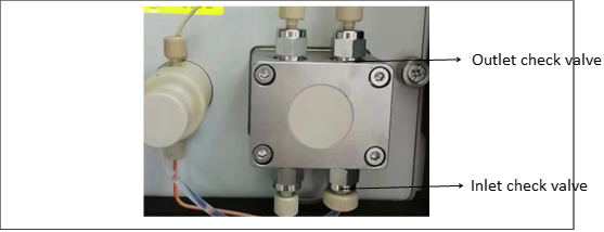
Figure 5-1
Pump check valve position
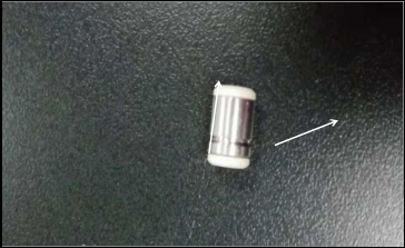
Figure 5-2
Inlet direction of check valve
 : Only when the direction of the check valve is correct can the infusion pump drive the liquid to flow to the flow path, otherwise the liquid cannot be sucked in. There is a coil on the inlet side of the unobstructed check valve. Liquid enters from the
coil side and exits from the loop-free side.
5.3.2 Replacement of check valve
1. Carefully disassemble the check valve according to the steps of cleaning the check valve;2. Install the new check valve according to the relevant procedures for cleaning the check valve. Be careful not to install it in the opposite direction.
5.4 Replacement of sealing ring or plunger rod
Damaged sealing ring or plunger rod will cause leak of pump body, unstable system flow path, increased baseline noise and other consequences. When such phenomena occur, replacement of sealing ring and plunger rod can be considered. The steps for replacing the pump sealing ring are as follows:1. Turn off the infusion pump and the main switch of the instrument power supply;
2. Unscrew the screws around the infusion pump counterclockwise to remove the infusion pump;
3. Unscrew the four screws of the pump head counterclockwise. The inside of the removed pump head is shown in the following figure. Carefully and gently remove the plunger rod and sealing ring after unscrewing;
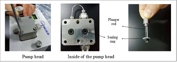
Figure 5-3
Replacement of the sealing ring
4. Replace the new plunger rod and the sealing ring and reassemble them completely.
:Any lateral movement will cause the plunger rod to break. The plunger rod should be operated vertically.5.5 Replacement of conductivity cell
1. Turn off the conductivity cell heating button, stop the pump and turn off the power supply of the instrument on the reverse control software;2. Disconnect PEEK pipeline and joint;
3. Use a screwdriver to remove the three screws on the conductivity cell;
4. Remove the conductivity cell from the DB joint;
5. Install new conductivity cell aiming at the pinhole of DB joint;
6. Tighten the fixing screws of the conductivity cell;
7. Reconnect the conductivity cell pipeline;
8. Power up the instrument again, turn on the pump to flush the conductivity cell and resume operation.
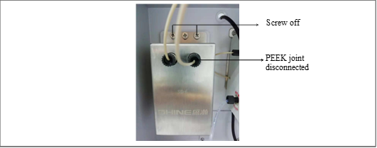
Figure 5-4
Replacement of conductivity cell
 : to avoid impurities in the pipeline in the new conductivity cell, the new conductivity cell needs to be rinsed with ultrapure water for about 12h first.
5.6 Replacement of amperometric detection cell gasket
When configuring the amperometric detector, replace the amperometric detection cell gasket as follows:1. Turn off the amperometric detection cell, stop the pump and turn off the power supply of the instrument;
2. Remove the connecting pipes and electrode connecting cables at the inlet and outlet of the amperometric detection cell;
3. Pull out the amperometric detection cell forward;
4. Loosen the fixing knob of the working electrode, clamp the clamping pins on both sides of the potential positioning block of the working electrode, pull the working electrode out of the positioning hole, and carefully remove it;
5. Use tweezers to peel off the old gasket from the cell body;
6. Wipe the cell body with clean, wet and fiber-free soft cloth;
7. Install new gasket, carefully check whether the gasket is flat and fit with PEEK cell body, and ensure that the two flow passage holes are symmetrically positioned in the center of the flow channel. Make sure that the gasket is free of wrinkles and bubbles;
8. Reinstall the working electrode fixing block and tighten the knob.
9. Reset the amperometric detection cell and connect cables and pipelines;
10. Turn on the pump and switch on the amperometric detection cell power supply after the pressure is stable.
: To avoid polluting the electrodes, dust-free gloves should be used foroperation.
5.7 Replacement Reference Electrode
The time limit of the reference electrode is about three months. The reference electrode should be soaked in saturated potassium chloride solution when not in use. When the noise is high or the response sensitivity is still low after polishing the working electrode, the reference electrode may be replaced.The operation steps are as follows:
1. Stop the instrument and dismantle the amperometric detection cell;
2. Loosen and remove the reference electrode;
3. Remove the protective cap of the new reference electrode (keep it well);
4. Flush the new reference electrode with ultrapure water;
5. Open the inlet and outlet joint of the amperometric detection cell and install the new reference electrode.
5.8 Replacement of the suppressor
New suppressors or suppressors that have not been used for a long time (more than one week) should be activated first.Activation step:
1. Connect the pump outlet directly to the REGEN IN port of the suppressor. Connect the REGEN OUT port directly to the waste liquid bottle. Inject deionized water at a flow rate of 0.3 mL/min for 10 min, and then seal with a plug;
2. Connect the pump outlet directly to the ELUENT IN port of the suppressor. Connect the ELUENT OUT port directly to the waste liquid bottle. Inject deionized water at a flow rate of 0.3 mL/min for 10 min, and then seal with a plug;
3. After sealing, leave for activation for not less than 30 minutes. Activation is completed.
Steps of replacing the suppressor:
1. Turn off the suppressor current and stop the pump;
2. Disconnect the suppressor cable and remove the pipe joint on the suppressor;
3. Remove the suppressor;
4. Install the new suppressor into the bracket (ELUENT OUT upward);
5. Connect the cables and reconnect all pipelines.
6. Start the pump and resume operation.
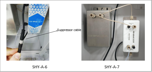
Figure 5-5
Replacement of the suppressor
:The joint of suppressor cable should be connected properly, otherwise no current will be applied.5.9 Replacement of the power fuse
1. Turn off the main power switch of the instrument and unplug the "pin" power plug at the rear end of the instrument;2. Use a flat screwdriver or other tools to gently remove the fuse fixing clip from the instrument;
3. Remove the fuse from the fixing clip and observe whether the fuse in the glass shell is broken in light.
4. If the fuse is broken, please replace the fuse of the same type and specification;
:Please do not replace other types of fuses at will. If you cannot confirm the fuse type, please contact the instrument manufacturer.5. In addition to the same specification and type, the new fuses in the glass shell should be in good condition and its metal shells at both ends should be free from rust.
6. During installation, ensure that the fuse is pushed into the original position after it
is in the middle of the fixing clip;
7. Connect the "pin" power plug of the instrument;
8. Turn on the instrument power switch;
9. Use the software or panel to see if the instrument returns to normal operation.
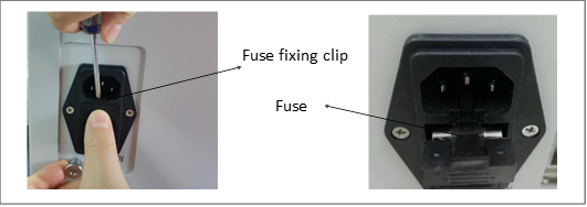
Figure 5-6
Replacement of the fuse
Through the above operations, if the instrument returns to normal operation, the fuse replacement is completed. If there is no normal operation, please check other possible causes of abnormal operation of the instrument.
5.10 Replacement of the eluent generator storage tank
When the instrument is equipped with an eluent generator, the operations to be performed when replacing eluent generator are as follows:1. Stop the pump and turn off the power supply of the instrument;
2. Remove the pipeline at the exhaust port above the eluent generation tank and seal the exhaust port;
3. Slowly lift the eluent generation tank and disconnect the cables and connected pipelines;
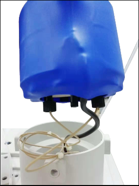
Figure 5-7
Pipeline connection of eluent generation tank
4. Open the two plugs of the new eluent generation tank and connect them to the pipeline. These two joints can be connected at will irrespective of outlet or inlet;
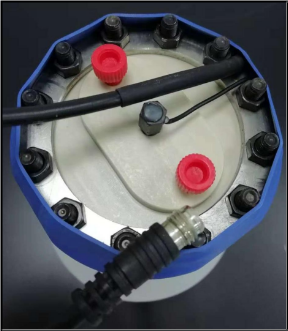
Figure 5-8
Plugs and cable of eluent generation tank
5. Connect the cable of the eluent generation tank completely;
6. Slowly reverse the eluent generator tank and place it in the generator tank bracket. Open the sealing cover at the exhaust port. When opening, the exhaust port should face the place with no one to prevent the gas generated by liquid shaking from rushing out of the bottle during transportation. Finally, connect the exhaust pipe and sink it below the water surface.
 :The eluent generation tank is filled with KOH or MSA solution with strong corrosivity. Please wear rubber gloves and goggles during operation to prevent burns.
5.11 Replacement of trap column
1. Turn off the power supply of the instrument;2. Slowly lift the eluent generation tube to expose the trap column below;
3. Disconnect the cable of the trap column and remove the surrounding pipeline;
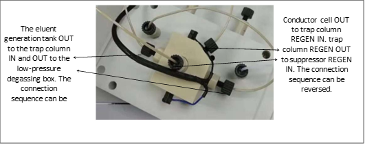
Figure 5-9
trap column pipeline connection
4. Connect the trap column pipeline and cable;
5. Recover the eluent generation tank;
6. Power on the instrument to resume operation.
A. Norms
A.1 Electrical correlation
| Main power supply | AC110-240V, 50Hz/60Hz, 150W |
| Fuse | 5*20mm, T6.3AL, AC250V |
Table 8
A.2 Physical correlation
| Dimensions (excluding eluent bottle and eluent generator) | Width*Length*Height: 345 *480*495mm |
| Weight | 26kg |
Table 9
A.3
| Temperature | 5-40℃ |
| Humidity | Relative humidity of 5% to 85%, non-condensing |
Table 10
A.4 Pump
| Model | Double piston, high pressure pump |
| Flow rate | 0.001-9.999 mL/min |
| Pump flow rate stability error | ≤1% |
| Pump flow setting value error | ≤1% |
| Running pressure | ≤42MPa |
Table 11
A.5 Conductivity detector
| Linear | Correlation coefficient>0.999 |
| Stability | ≤3% |
Table 12
A.6 Conductivity cell
| Cell body material | PEEK |
| Electrode material | 316 Stainless steel |
| Running temperature | Ambient+ 5-60℃ |
| Max pressure | ≤10 MPa |
Table 13
A.7 Valve
| Six way valve | PEEK material, six-holes, electromagnetic trigger |
| Pressure | ≤35MPa |
Table 14
A.8 Column heater
| Running temperature | Room temperature +5-85℃, set according to the temperature required by the analytical column |
B. Installation
B.1 Equipment requirements
1. Ambient temperature: 5℃ to 40℃2. Relative humidity: relative humidity of 5% to 85%, non-condensing
3. The room should be clean and well ventilated. The instrument should be stably placed on the workbench without strong mechanical vibration and electromagnetic interference sources.
4. The instrument should be well grounded.
B.2 Unpacking
Unpack the instrument and check whether the equipment and accessories are damaged during transportation. If damaged, the carrier company should be provided with a statement of responsibility in time.Check and count the articles against the packing list. If there are any omissions or errors, please contact us in time.
: since the instrument is heavy, please ask two or more people to carry the instrument together and lift the bases on the left and right sides of the instrument. It is forbidden to lift the front side and rear side, otherwise the soundness of the front door will be damaged. : Do not contact sharp objects to avoid scratching the surface coating of theinstrument.
: the power supply current used by this instrument is large, which may cause personal injury such as electric shock. Therefore, please turn off the power supply and unplug he power cord before handling. When handling the instrument, please fasten the casing of the instrument. It is forbidden to move the protective casing of live equipment such as circuit boards.B.3 Installation software
1. Start the computer;2. Insert the USB disk into the computer;
3. Select the working software;
4. Click the setup program, select the installation address, and install according to the installation wizard.
5. Select whether to create a shortcut. If selected, the shortcut will be automatically rebuilt on the desktop.
6. The final display of "Finished" indicates that the software has been successfully installed. NOTE:Refer to section 3.
B.4 Connecting the instrument to computer
The BCHR-102 instrument is connected with the computer through a data line.1. Take out the data cable in the instrument accessory box;
2. Connect the DB fitting end of the data cable into the DB socket on the rear panel of the instrument, and connect the USB end into the USB socket of the computer end.
B.5 Connecting the autosampler to the instrument (optional)
The autosamplers produced by us have the same connection mode as that of the instrument pipeline. Compared with the mode of not using an autosampler, it is only necessary to connect the pipeline at the outlet of the trap column to the valve port 2 of the autosampler injection valve and connect the valve port 3 to the inlet of the Guard column. And the connection of the other pipelines is the same as that when the autosampler is not connected.B.5.1 Steps for connecting SHA-9 to instrument trigger line
1. Take out the trigger wire in the instrument accessory box;2. Connect one end of the trigger line to the trigger port of the autosampler and connect the other end to the autosampler port of the instrument;
3. Align the notch of the trigger line upward to the trigger port. When connected, if the groove is perceived to be clamped in, the connection is completed.
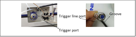
Figure B-1
SHA-9 trigger port
B.5.2 Step for connecting SHA-16 autosampler to computer
SHA-16 autosampler, data transmission, using RS232 data line, only connected to the "① communication" port.The other side of RS232, connect the computer USB port.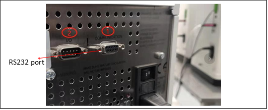
Figure B-3
SHA-16 Rear Panel
Please refer to the user manual of SHA-16 autosampler for details.
B.6 Connecting power cord
Connect the power cord from the main power socket of the instrument rear panel to the grounding power supply. The instrument power supply is automatically induced, so the selected line voltage does not need to be adjusted. : To avoid electric shock, please use grounded socket. Do not operate the instrument without grounding.
B.7 Installation of chromatograph column and suppressor
This section will briefly introduce the installment of chromatograph column and suppressor. Before starting the installation, please carefully read the user manual in the packing box to understand the detailed use of the chromatograph column and suppressor. Unpack the packing box and take out the protective cover, chromatograph column and suppressor, and remove the sealing plug.B.7.1 Installation of chromatograph column
1. Connect the Guard column according to the liquid flow direction marked by the Guard column under the condition that the pipeline normally flows out liquid;2. Connect the chromatograph column after the liquid flow at the end of the Guard column is normal. Connection of the chromatograph column should be performed according to the marked liquid flow direction by the chromatograph column.
3. After the connection is completed, put the guard column and chromatograph column into the clamping groove;
1. Finally, fasten the front cover of the column oven.
 : When installing the chromatograph column, the pump flow rate should be
reduced to 0.3mL/min or less. When the new chromatograph column is connected to the chromatograph system for the first time, first flush it with water and eluent and disconnect the conductivity cell and suppressor to prevent high conductivity substances or bubbles from entering the conductivity cell or suppressor. When the outlet end of the chromatograph column flows out clean and bubble-free liquid, connect the conductivity cell and suppressor.
B.7.2 Installation of suppressor
1. Connect the pipeline from the chromatograph column to the ELUENT IN interface of the suppressor;2. Connect the suppressor ENLUENT OUT joint to the IN interface of the conductivity cell;
3. Connect the OUT interface of the conductivity cell to the REGEN IN interface of the trap column;
4. Connect the trap column REGEN OUT interface to the suppressor REGEN IN interface;
5. Connect the suppressor REGEN OUT interface to the waste liquid pipe;
6. After all pipelines are connected, put the suppressor REGEN OUT interface upward and hang the suppressor onto the suppressor support in the instrument.
B.8 Connecting waste liquid pipes
BCHR-102 instrument waste liquid pipe includes the following four types:1. The back flushing waste liquid pipe of the advection pump discharges the waste liquid from the flushing pump head;
2. The waste liquid pipe of the injection valve discharges the excess sample during injection;
3. The suppressor waste liquid pipe discharges the waste liquid finally generated in the flow path;
4. The waste liquid pipe of the eluent generator discharges the gas generated in the eluent generator tank.
: To prevent siphoning of waste liquid, please check whether the waste liquid pipe is bent, squeezed or raised at any time.B.8.1 Installation of waste liquid pipes
1. Connect all pipelines of the instrument;2. Collect all waste liquid pipelines into a thicker pipeline;
3. Put the waste liquid collection pipe into the waste liquid bottle.
: The waste liquid bottle should not be sealed because the continuous self-regeneration suppressor uses electrolysis to suppress the background during the operation of the instrument and a small amount of oxygen and hydrogen will be generated during electrolysis. Gas should be prevented from staying in the waste liquid bottle so as notto generate static electricity. In serious cases, there may be explosions.
B.9 Installation of eluent bottle
1. Rinse the eluent bottle with ultrapure water;2. Load the eluent into a eluent bottle;
3. Place the eluent bottle in the eluent tray at the upper end of BCHR-102;
4. After installing the filter head, put the pipeline into the eluent bottle and tighten the eluent bottle cap.
: BCHR-102 instrument does not require pressure-protected eluent bottle. However, if the eluent is degassed manually or easily contaminated, it is recommended to equip the eluent bottle with nitrogen protection.B.10 Flushing pump
Before flushing, ensure that the eluent bottle is full of eluent; the eluent bottle cap is tightened; the eluent pipeline is connected and the waste liquid pipe is inserted into the waste liquid bottle.B.10.1 Flushing pump head
: Caution: When the instrument is used for the first time, for a long time, or when it is not normally used, the pump head should be rinsed clean to avoid residual crystals in the pump head damaging the pump head.The flushing steps are as follows:
1. Connect the back flushing pipeline of the pump body;
2. Use a 10 mL injector to suck up ultrapure water and connect it to one end of the flushing pipeline, and insert the outlet pipeline into the waste liquid bottle;
3. Slowly push the injector to clean the pump head. This operation can be repeated several times.
B.10.2 Flushing eluent pipeline
:When installing and replacing the eluent for the first time or when there is no liquid in the eluent pipeline, the eluent pipeline should be flushed.The flushing steps are as follows:
1. Insert a 10 mL injector into the curved needle beside the exhaust valve;
2. Turn the exhaust valve counterclockwise for 1/4-1/2 turn to start the exhaust valve;
3. Draw the injector or control the flow rate of the pump to 1 mL/min, and slowly pump out the gas in the pipeline or the eluent before replacement;
4. Keep pumping until about 20 mL of new replacement eluent is extracted to ensure that the gas and residual eluent in the pipeline have been completely drained away;
5. Finally, adjust the flow rate to normal and tighten the exhaust valve clockwise.
B.11 System balance
1. When the pump flushing is finished, turn on the pump and gradually set the pump flow rate to the operating speed;2. Flush the pipeline for about 30min to balance the flow path of the whole system;
3. Monitor the pressure fluctuation of the pump by looking at the pump window or reverse control software;
4. Confirm whether the eluent flow path finally flows out from the REGEN OUT end of the suppressor and whether the pump pressure is stable;
5. Confirm whether the background baseline conductance is normal.