


Forced Convection Oven BOFC-5401
- Sea, Air, Door to Door Shipping
- 1 Year Warranty
- US & European Standards
- With reservation and Timer functions, there is no need to wait, which effectively improves the efficiency of the experiment
- Available in Chinese and English menus to meet different language needs, with °C / °F conversion
- The height of the shelf is adjustable to meet different cultivation needs
- Professional stacking foot design, the machine can be stacked, saving lab space and improving the use efficiency
Specification
Features
| Capacity | 35 L |
| Temperature Range | RT+10°C-200°C (MAX 300°C) |
| Display Resolution | 0.1°C |
| Uniformity at 100°C | ±2.0°C |
| Heated to 100°C | 25 mins |
| Standard Max number of shelves | 2 (5) |
| Max load per shelf | 20 Kg |
| NW | 43 Kg |
| Timer Range | 1 - 5999 mins |
| Internal Dimension | 320Wx350Dx320H mm |
| Exterior Dimension | 610Wx550Dx540H mm |
| Electrical Requirement | AC 220 V, 50 Hz |
| Power Consumption | 900 W |
- With reservation and Timer functions, there is no need to wait, which effectively improves the efficiency of the experiment
- Available in Chinese and English menus to meet different language needs, with °C / °F conversion
- The height of the shelf is adjustable to meet different cultivation needs
- Professional stacking foot design, the machine can be stacked, saving lab space and improving the use efficiency
- Protection on instruments: Comply international standard secondary temp limiting alarm system, when the heating is out of control or exceeds the maximum limit temperature
- the heating is automatically cut off with sound and light alarm, ensure operating is safe without any accident
- Protection on key components: Key components are equipped with over-current, over-temperature, overload and other safety protection to prevent accident
- Protection on samples: When the temperature inside the box is higher or lower than the set temperature, the alarm will start to cut off the heater, with sound and light alarm to remind the operator to protect the sample from normal test without accident
- Protection on operato: The cabinet and door are specially insulated to make the surface temperature of the cabinet low, ensuring the operator's safety and no accidents
- Breakdown message provided: When the instrument breakdown, the message will shown on the screen to help operator clearly check
- The touch screen type standard with a USB interface, which can record the change status of the temperature parameters
- The LCD screen is option for USB interface
- It can be equipped with RS232 data interface, which can realize remote control of the machine through software
- RS-232 and USB can be selected one of them
Operating Manual for BOFC-5401
1.Warranty
2.Contents of package
3. Installation requirements and safety tips
3.1 Installation requirements
3.2 Instruction for Safety
4.Product introduction
4.1 Function introduction
4.2 Specifications
5. Temperature and timing setting
5.1 Display
5.2 Operation
6. Clean and maintenance
7. Troubleshooting Guide
1.Warranty
Thank you for purchasing a Being instrument. In normal use conditions, the instrument is guaranteed for a period of 24 months from the date of purchase.The warranty is valid only if the product is original. It does not apply to any product or parts of it that have been damaged due to incorrect installation, improper connections, improper use, accident or abnormal conditions of operation.
The manufacturer declines all responsibility for damage caused by failure to follow instructions, lack of maintenance and any unauthorized modification.
2.Contents of package
The instrument is delivered complete with the following parts:Drying Oven (main unit)
2 stainless steel wire shelves
4 brackets for shelves
Power supply cable
User manual
3. Installation requirements and safety tips
3.1 Installation requirements
The incubator should be installed in follow conditions:1. Dry, clean and stable work table with a flat horizontal surface.
2. Respect minimum spaces around instrument 80 cm.
3. Room temperature between 41°F(5°C)and 104 °F(40°C), and relative humidity maximum of 85%.
4. Power supply socket with earth connection.
5. Power feed between 110V-120V–60Hz. (220V – 60HZ for BONC-5604, BOFC-5404, BOFC-5405).
3.2 Instruction for Safety
3.2.1 Danger!
The improper use of this unit may cause property damage and/or personnel injury.
1. The product must be properly electrically grounded (The Hot line or the Neutral line should not be the grounded connection adhere to the product’s requirement before using).
2. Please ensure the voltage and frequency of the power supply are compatible with the incubator power requirements prior to use. The fluctuations of the supply voltage shall not exceed 10% of the nominal supply voltage.
3. This unit must use the included electrical cord with a dedicated electrical circuit with a confirmed electrical ground connection.
4. The power switch MUST be in the “OFF” position when power is connected or disconnected from unit.
5. Do not arbitrarily lengthen or shorten the power supply connection wire. Do not modify the power cord in any way.
6. It is prohibited to put in flammable, explosive, volatile, and corrosive substances for drying and baking.
7. Do not touch the chamber door, the chamber body or the surrounding surface when the set temperature is over176°F(80°C)!
8. Do not put hands or objects into the air inlet or air outlet.
9. The unit should have routine inspections and should be serviced by a qualified service technician when needed.
3.2.2 Warning!
1. Please use the socket connecting with the ground connection to prevent electric shock. If the socket does not have the ground connection, the earth wire must be installed by the qualified electrician. Be sure not to conduct the ground connection through the gas pipe, water pipe, telephone line or lightning rod! This kind of ground connection may cause electric shock due to the incomplete loops.
2. 304 stainless steel material is not acid resistance, so please pay attention to the corrosion prevention measures. Never place corrosive materials inside the unit to prevent damage
3. Do not tension the power supply cord when plug in.
4. The power cord must be removed from receptacle when any of the following occur:
When replacing the fuse;
When the product is waiting for overhaul due to faults;
When the product goes out of service for a long time;
When the product is being moved;
3.2.3 Caution!
1. The incubator should be located on a strong solid surface.
2. Take care when opening and closing the door to prevent damage to delicate internal components.
4.Product introduction
4.1 Function introduction
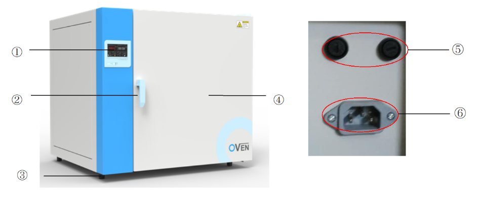
Figure 1
Control system Opening / Closing handle Support foot Box door Circuit Breaker Power outlet
4.2 Specifications
Forced Air Drying Oven| Model Parameter | BOFC-5401 | BOFC-5402 | BOFC-5403 | BOFC-5404 | BOFC-5405 |
| Chamber Volume | 35L | 59L | 115L | 234L | 400L |
| Temperature Range | Ambient+10℃~200℃ | ||||
| Temperature Stability | ±1℃ | ±1℃ | ±1℃ | ±1℃ | ±1℃ |
| Display Resolution | 0.1℃ | 0.1℃ | 0.1℃ | 0.1℃ | 0.1℃ |
| Standard Quantity of Shelves | 2 | 2 | 2 | 2 | 3 |
| Maximum Quantity of Shelves | 5 | 9 | 12 | 16 | 16 |
| Shelves loading | 20Kg | 20Kg | 20Kg | 20Kg | 20Kg |
| Net Weight | 43 | 51 | 83 | 112 | - |
| Timer | 1~5999mins | 1~5999mins | 1~5999mins | 1~5999mins | 1~5999mins |
| Internal Dimension (W*H*D, mm) | 320*320*300 | 400*415*305 | 520*530*430 | 650*650*500 | 1000*800*510 |
| External Dimension (W *H*D, mm) | 610*540*550 | 690*640*560 | 810*755*685 | 940*875*750 | 1285*1060*750 |
| Electrical Requirement | AC220V,50Hz | AC220V,50Hz | AC220V,50Hz | AC220V,50Hz | AC220V,50Hz |
| Power Consumption | 900W | 1100W | 2050W | 2500W | 3100W |
Table 1
Natural Convection Drying Oven
| Model Parameter | BONC-5601 | BONC-5602 | BONC-5603 | BONC-5604 |
| Chamber Volume | 34L | 54L | 124L | 222L |
| Temperature Range | Ambient+10℃~200℃ | |||
| Temperature Stability | ±1℃ | ±1℃ | ±1℃ | ±1℃ |
| Display Resolution | 0.1℃ | 0.1℃ | 0.1℃ | 0.1℃ |
| Standard Quantity of Shelves | 2 | 2 | 2 | 2 |
| Maximum Quantity of Shelves | 5 | 6 | 10 | 16 |
| Shelves loading | 20Kg | 20Kg | 20Kg | 20Kg |
| Net Weight | 43 kg | 45 kg | 74 kg | 103 kg |
| Timer | 1~5999mins | 1~5999mins | 1~5999mins | 1~5999mins |
| Internal Dimension (W *H*D, mm) | 320*320*300 | 400*380*330 | 520*495*450 | 650*650*500 |
| External Dimension (W*H*D, mm) | 610*580*520 | 690*640*468 | 810*755*590 | 940*910*658 |
| Electrical Requirement | AC220V,50Hz | AC220V,50Hz | AC220V,50Hz | AC220V,50Hz |
| Power Consumption | 850W | 1050W | 1950W | 2250W |
Table 2
5. Temperature and timing setting
5.1 Display
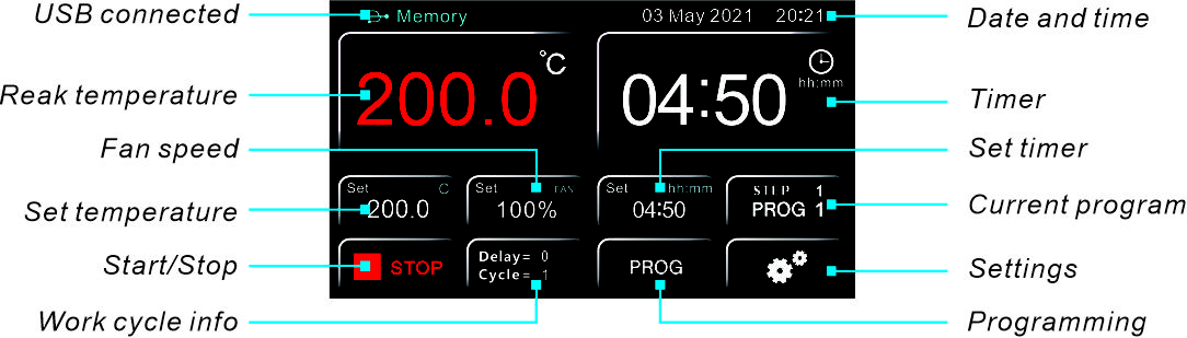
Figure 2
The touch screen display is resistive, so it is possible use it indistinctly with your fingers, wearing latex gloves, with pens equipped of rubber terminal, with generic pens or pencils.
5.2 Operation
Switching on the instrumentConnect the power cord to a power outlet with a protective ground connection.
Turn on the instrument by pressing the button ON/OFF. Button and the display light
The display shows the initialization sequence with “LOGO” and software version.
Basic mode (PROG 0) or with Programs (PROG 1...8)
The instrument can work in two modes:
- Basic (PROG 0): program with a single working step.
- Programs (PROG 1...8): eight memorized programs, each of which consists of 8 steps
In both versions it is always possible to set the temperature, the timer and the fan speed (if present) for each individual work step.
Depending on the program in which you are located, the display will show one of the following main screens:
- PROG 0: Figure 4
- PROG 1: Figure 5
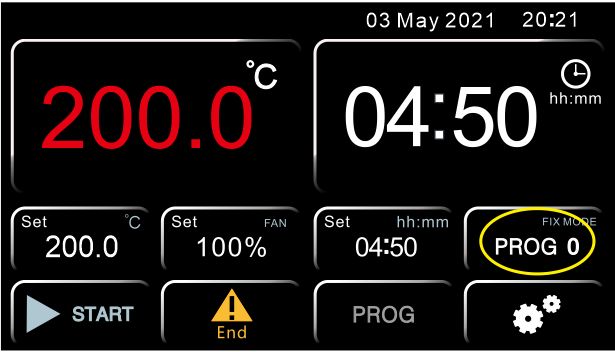
Figure 4
Main screen PROG 0
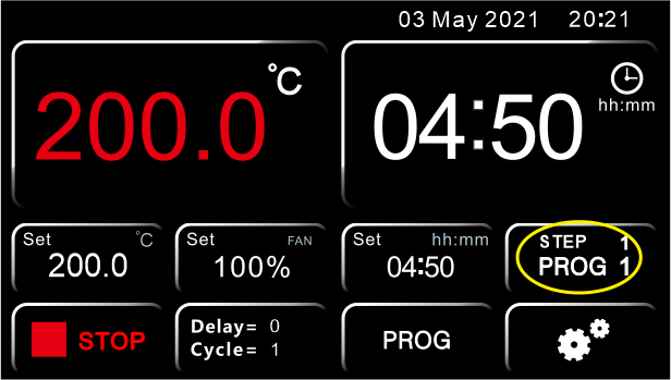
Figure 5
Main screen PROG 1
Recall and selection of a program
To select the desired program, press the highlighted key in Picture 4 – Main screen PROG 0or Picture 5. As mentioned, it is in the same position, the only change is the content of the screen depending on the program in which you are located.
Then, one of the two screens will appear(Figure 6 and 7)
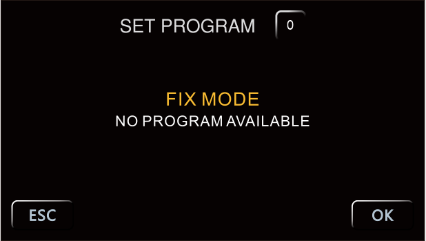
Figure 6
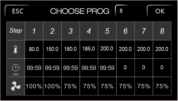
Figure 7
The PROG 0 is with a single step, therefore the indication “FIX MODE–NO PROGRAM AVAILABLE”, while the programs from one to eight have eight steps each one (Figure 7)
Programming
Modification of working parameters PROG 0
From the main screen of the PROG 0 mode (Picture 9), press the highlighted keys to change, from left to right, the temperature, the fan speed (where present) and the timer respectively. The screens of Picture 10, Picture 11 and Picture 12 will therefore appear.
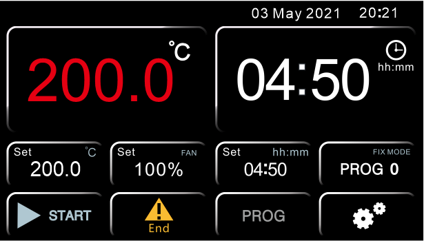
Figure 8
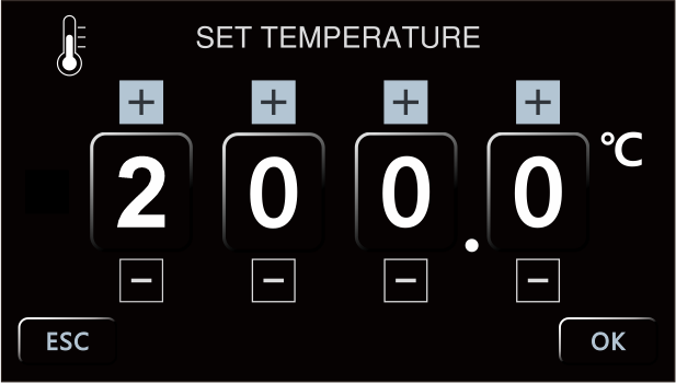
Figure 9
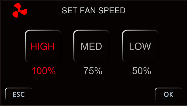
Figure 10
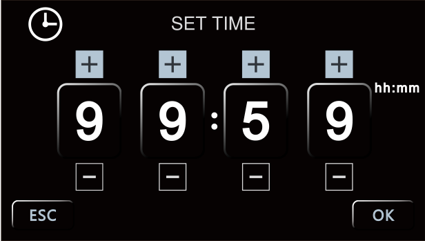
Figure 11
To increase or decrease the values of temperature and time, use the keys + and -, while for the fan (if present) it is possible choose directly between three speeds: High (100%), Medium (75%) e Low (50%).
In all the screens it is necessary confirm the set value by the button OK.
NOTE: it is possible to return to the previous screen without saving the modification pressing ESC.
Modification of working parameters PROG 1...8
From the main screen (Picture 12) press PROG to access to the menu of (Picture 13).
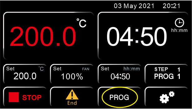
Figure 12
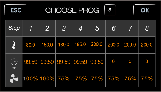
Figure 13
In the screen of Picture 14, select the program that you want to change by pressing the yellow highlighted button and setting the corresponding digit using the numeric keypad. Confirm with ENTER.
For each individual program step (from 1 to 8) it is possible to set the temperature (degrees Celsius), the timer (minutes) and the fan speed (if present), by clicking on the buttons highlighted in green, red and pink of the same screen.
For the temperature and the timer, the respective numeric keypads will appear, marked by the icon of the thermometer (Figure 14) and the clock (Figure 15), with the indication of the program and of the step being modified. Once the desired value has been set, confirm with ENTER or go back to the previous screen without saving the changes by pressing ESC.
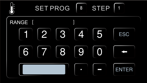
Figure 14
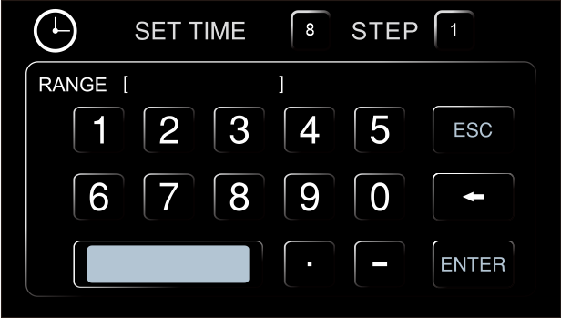
Figure 15
To change the fan speed (if present), instead, simply click on the corresponding button (pink color in Figure 13) and the value will change in sequence between 100% = High, 75% = Medium and 50% = Low.
REPEAT THE PREVIOUS INSTRUCTIONS FOR EVERY STEP YOU WANT TO PROGRAM
NOTE: if you do not want to use all the STEPs of the program you are editing, it is necessary to impose the end of the program to the instrument. To do this, simply set a time equal zero in the next step to the last one you want to use.
EXAMPLE of Figure 13
If the last work step to be used is the third, it is enough to set the timer equal 0 in the fourth step, thus imposing that instrument stops after third step.
Start/stop of a program
To start or stop a program press respectively the START key (Figure 16) or STOP key (Figure 17). The keys are the same in both the main screens (PROG 0 or PROG 1...8).

Figure 16
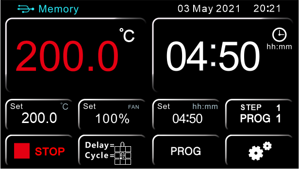
Figure 17
The instrument then starts the set work cycle which can be one or more steps.
NOTE: the timer countdown only starts when the set temperature is reached. To be precise when T real = T set ± 0.3 ° C.
Observing Figure 20, for example, the countdown of 99 hours and 59 minutes will start when the instrument reaches 200 ± 0.3 ° C
At any time, it is possible to check the work step and the program number in which you are located (in green Figure 18 and Figure 19), as well as the possible delay at the start that has been set (Delay) and the number of repetitions of the program executed (Cycle), highlighted in blue Figure 18 and Figure 19.
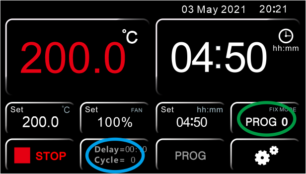
Figure 18
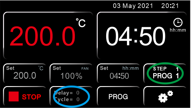
Figure 19
NOTE: it is always possible to consult the various parameters set in the steps of the program in use by clicking on the green button in Figure 18 and Figure 19, but be careful to press ESC only to return to the main screen. If you press the OK key, the instrument will interpret the action as confirmation of the choice of a new program, therefore it will forcedly terminate the work cycle in progress.
When the program ends or is manually stopped, the word "End" appears on the main screen (Figure 20) together an intermittent acoustic signal, which can be silenced by pressing the word "End" itself.
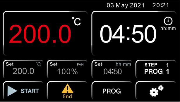
Figure 20
Pressing the icons of the gears of Figure21 and then the key USER (Figure 22), you access to the user settings menu screens (Figure 23 and Figure 24).
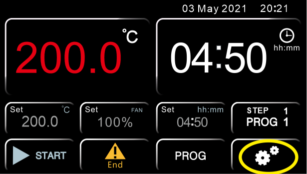
Figure 21

Figure 22
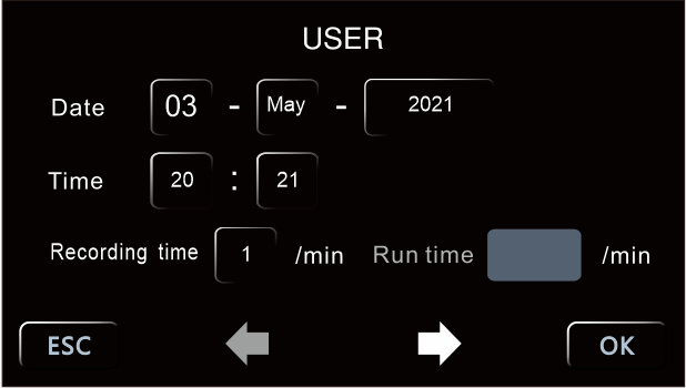
Figure 23
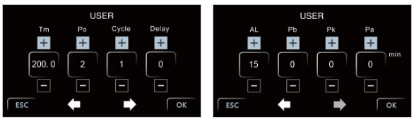
Figure 24
Settings of date and time
Clicking on any key of date and time you access to the menu of Figure 25
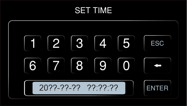
Figure 25
Set the date and time using the numeric keypad minding that the format is as follow:
20yy-mm-dd hh: mm: ss
NOTE: It is necessary to set all the parameters (date and time) each time.
Frequency of data recording
Click on the highlighted key of Figure 26 to modify the frequency with which the instrument records the data of the work cycle.
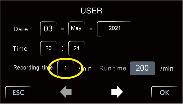
Figure 26
Using the numeric keypad set a time (in minutes) from 1 to 255. Press ENTER to confirm or ESC to go back to the previous screen without saving.
NOTE: the memory can contain up to 2000 recordings. When this limit is reached, the instrument will start to overwrite the same memory with new data, thus erasing the previous ones starting from the oldest ones.
The recording frequency thus also defines the recording capacity in terms of duration (example Frequency= 60 minutes → 2000 data x 60 minutes= 2000 hours= 83 days).
NOTE: if a USB stick is connected to the instrument, the recordings take place directly on it as well as in the instrument's memory. The memory limit of 2000 data remains however, but the key itself will act as secondary memory and therefore it is possible to make a continuous recording over 2000 data.
Tm:Safety temperature limiter for samples protection
The instrument has the possibility to limit the maximum work temperature (Tm) for the samples protection from an erroneous setting of the working temperature.
On the top left part of display in Picture 25 the parameter “Tm” (temperature max) and the maximum expected value for the kind of instrument (different for oven and incubator) appear.
Set the maximum temperature value you want the instrument doesn’t exceed during work cycle pressing on corresponding box and using the numeric keypad. Press ENTER to confirm or ESC to return to the previous screen without saving.
Example
If the set temperature for the work cycle is 100 °C and the temperature limiter (Tm) is fixed at 70°C, the instrument tries to achieve the set temperature (100°C), even if it is higher than the limited one set in this menu (Tm).
When the 70 °C are achieved the instrument goes in alarm emitting an audible intermittent alarm (silenced by pressing the Alarm key) and the heating element doesn’t receive power supply until to the temperature will go below the limited one (Tm).
NOTE: the instrument tries in any moment to achieve the set work temperature, therefore, until it is bigger than the limited one (Tm), it goes in overtemperature alarm.
Po:Restart mode after absence of power supply
It’s possible to set the restart mode of the instrument after a power supply absence (Po):
| Po VALUE | DESCRIPTION |
| 0 | On return of the power supply, the instrument does not automatically resume the heating cycle, but you must manually restart. |
| 1 | On return of the power supply, the instrument automatically resumes operation from the beginning of the heating cycle interrupted |
| 2 | On return of the power supply, the instrument automatically resumes operation at the very point of the heating cycle in which it was interrupted |
Table 3
Set the desired value pressing on the corresponding box (Figure 24) and using the numeric keypad. Press ENTER to confirm or ESC to return to the previous screen without saving.
AL: Temperature limit for over temperature alarm
The instrument permits to set the limit of temperature over which it goes in over temperature alarm (AL).
NOTE: even if this value is adjustable by the operator, it’s already set by factory and perfectly calibrated in function of instrument type, natural/forced air oven or incubator.
We recommend to do not change this value unless absolutely necessary, because temperature fluctuations more or less than the set one, especially in natural convection models, are normal and thus reducing dramatically the value of AL, it would risk do go frequently and unnecessarily alarmed the instrument.
If the modification is desired, press on the corresponding box (Figure 24) and use the numeric keypad. Press ENTER to confirm or ESC to return to the previous screen without saving.
Temperature offset on single point, on entire ramp, on room sensor
The instrument permits set the offset value on a single temperature point (Pb), on the entire temperature ramp (Pk) and on the room temperature (Pa).
NOTE: even if these values are adjustable by the operator, they are already set by factory and perfectly calibrated with certified and referable Accredia’s measurement instruments.
We recommend that you do not change these values unless strictly necessary, for example if after a check with digital certified thermometer you find a discrepancy between the readings of the instrument and the external thermometer.
| Parameter | DESCRIPTION |
| Pb | Changing this parameter, you can correct the reading of PT100 sensor inside the instrument on one point temperature. The correction will therefore be attributable to one specific point. |
| Pk | Changing this parameter, you can correct the reading PT100 sensor inside the instrument over the entire temperature ramp, that is going to change the inclination of the ramp reading of the sensor. |
| Pa | Changing this parameter, you can correct the reading of environmental PT100 sensor installed on the instrument (only refrigerated versions) on only one temperature point. The correction will therefore be attributable to one specific point. |
Table 4
If the modification is desired, press on the corresponding boxes (Figure 24) and use the numeric keypad. Press ENTER to confirm or ESC to return to the previous screen without saving.
Delay of heating cycle start
The instrument provides the possibility of setting a delay at the start of the operating cycle (Delay) from 1 to 9999 minutes.
Set the desired value by pressing the corresponding box (Figure 24) and using the numeric keypad. Press ENTER to confirm or ESC to return to the previous screen without saving.
Once the delay has been set, by pressing the START key the instrument starts the program, but does not immediately start to heat up. Once the set delay time has elapsed, the instrument starts the heating and the set timer appears on the display.
Repetition of the selected program
The instrument allows the repeating from 1 to 99 times of the selected program, function (Cycle).
NOTE: it’s also possible set the continuous repetition of a program, setting it in continuous “loop”, with the parameter Cycle=0.
Set the desired value by pressing the corresponding box (Figure 24) and using the numeric keypad. Press ENTER to confirm or ESC to return to the previous screen without saving.
Download data and USB pen
The instrument is equipped as standard with a USB port for connecting a pendrive (Picture 28). By connecting a USB stick when the instrument is switched on (with active or inactive work cycle), the automatic download of all the data that the machine has in memory takes place (without having to press anything).
NOTE: if a USB stick is left connected to the instrument, the recordings take place directly on it as well as in the instrument's memory. The memory limit of 2000 data remains however, but the key itself will act as secondary memory and it is therefore possible to make a continuous recording over 2000 data.
The format of the files that are downloaded is of type .txt. The data are therefore completely "open", editable and transferable to the normal computers’ applications, and it is possible to process them by the operator independently, without the need of any dedicated software.
6. Clean and maintenance
• Proper maintenance and cleaning of the instrument guarantee its good conditions.• The inner chamber of the instrument is made of stainless steel, so it can be cleaned with any detergent provided it is not aggressive and / or corrosive.
• You should clean the inside and outside surfaces with a standard all-purpose cleaner sprayed on a soft cloth.
• Before proceeding with any cleaning or decontamination, the user must ensure that the method used does not damage the instrument.
IMPORTANT
If the instrument must be returned for service, it is necessary to provide for proper cleaning and possible decontamination by pathogens of the same.
It is also recommended to put the instrument in its original packaging to send it in for repairs and if it is missed it is necessary to provide to pack it properly in order to the transport.
Any damage caused from the incorrect shipping will not be covered by warranty.
7. Troubleshooting Guide
| Symptoms | Possible causes | Remedies |
| No power after startup (pilot lamp is not on) | Power socket is not energized or plug is in poor contact. | Make it repaired. |
| Chamber power line broken or plug is not inserted properly. | Make it repaired or inserted again. | |
| Power switch is broken (or is not turned on) | Make it fixed by the professional personnel. | |
| Fuse blown | If the fuse still burned out after the replacement and energization, you need to check if the switch, heater or temperature controller are short-circuited or leaked (insulation resistance of 0) and restart after repairing. | |
| The temperature displayed abnormal on the screen | Sensor is out of order or wiring is broken (knocked off) | Pt100 is repaired or replaced. |
| No temperature rise | Check if timing is set up and time is up. | Refer to the operation of timing function. |
| The controller does not work (without output) | When OUT light doesn't shine or 3061 is broken, replace it. | |
| Setting temperature is lower than the internal temperature | Open the door until the internal temperature is lower than the setting temperature. | |
| Temperature control is inaccurate (static difference is large) | The difference between room temperature and set temperature is less than 5 degrees Celsius. | Minimum temperature under control :Ambient+5℃(9℉) |
| Noise abnormal (BOF series) | The fan is broken or lack of lubricating oil | Replace fan or add lubricating oil |
| Friction on rear air duct plate | Repair or add washer |
Table 5