


Cooled Incubator BICL-7905
- Sea, Air, Door to Door Shipping
- 1 Year Warranty
- US & European Standards
- 304 stainless steel, mirror polishing processing, easy to clean and maintain
- PID controller with over temperature alarm and timing function ensures precise and reliable control, also guarantee an excellent control by microprocessor and the limited number of setting keys ensures an extremely simple and intuitive operability
- The inner lamp for observation of the samples is standard supplied
- 3 fan speed meets all requirements of different experiments
Specification
Features
| Capacity | 248 L |
| Temperature Range | 0 - 60°C |
| Display Resolution | 0.1°C |
| Temperature Stability | HIGH ±0.5°C LOW±1.0°C |
| Temperature Uniformity | ±1.5°C |
| Electrical Requirement | 220 V 50 Hz |
| Ambient Temperature | +5°C - 30°C |
| Power Consumption | 600 W |
| Interior Dimension | 540Wx460Dx1000H mm |
| Exterior Dimension | 637Wx662Dx1590H mm |
| Shelves | 3 pcs |
| Timing Range | 0~5999 min |
- 304 stainless steel, mirror polishing processing, easy to clean and maintain
- PID controller with over temperature alarm and timing function ensures precise and reliable control, also guarantee an excellent control by microprocessor and the limited number of setting keys ensures an extremely simple and intuitive operability
- The inner lamp for observation of the samples is standard supplied
- 3 fan speed meets all requirements of different experiments
- Famous brand compressor with refrigerant R134a
Operating Manual for BICL-7905
1. Prompt for safety
2. Brief Introduction
2.1 Outside View
2.2 Outline of Structure and Functions
3. Application
4. Maintenance and Instructions
5. Appendixes
Packing List
 A prompt for safety assurance
Items enclosed here are extremely important, and must be observed faithfully.
1. Prompt for safety
! Dangerous(It might cause serious loss of property or personnel casualty)1. The product must be earthed reliably and keep far from the interruption of electromagnetism (be sure not taking the zero line and neutral line as earthing line).
2. Before putting into use, confirm that the voltage of power supply is in conformity with the specification of the product.
3. An individual power socket shall be provided for this product, and ensure the earthing for plug and socket is all right.
4. It is not allowed to pull out or plug in the power plug without turning off the power switch during the operation of the product.
5. It is forbidden to extend or cut short the power cable at will.
6. It is not allowed to make bold to repair the product. In case of entrusting repair by our company, the work must be done by professional staff.
! Warning(It might cause heavy loss of property or personnel casualty)
1. It can be operated only after the instruction manual is fully read and understand.
2. Please do not draw the power cable when pulling out the plug.
3. The power plug of this product must be pull out in case of one the following cases:
3.1 Replacing fuse tube;
3.2 The product goes wrong and standing by for inspection and repairing;
3.3 The product will not be used for long time;
3.4 When moving the product;
! Notice It might affect the service life and lead to malfunction of the product)
1. In case of handling the product, the obliquity should not be large than 45°, so as not to damage the refrigeration system.
2. When the product is transferred to the position, it shall be shelved for one to two days before operation, so as to allow the refrigeration system working in normal condition and extend its service life.
3. The product shall be set on rigid and firm plane to keep it at level status.
4. Enough space shall be remained around the product.
5. The product must be used under a certain condition.
6. Don’t open/close the door rudely, or it will result in fall off of the door, damage of the product and injury accident.
7. In case the product is shelved for a long time, the humidity elimination shall be done regularly to prevent relevant parts from damaging.
2. Brief Introduction
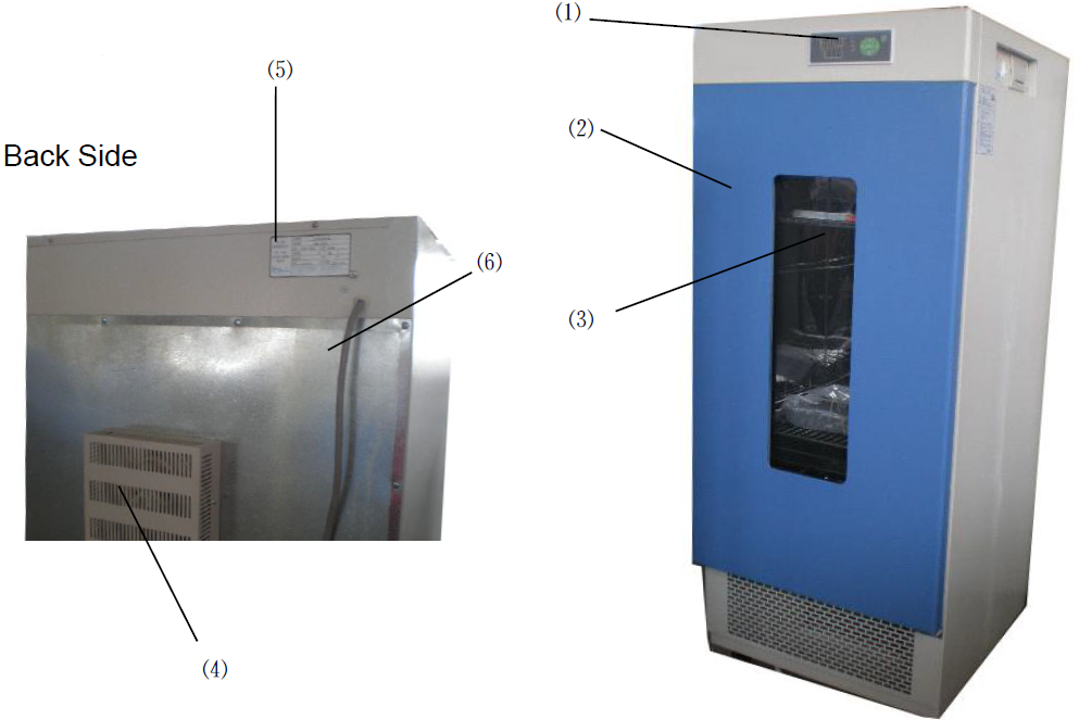
2.1 Outside View
150 Series
Figure 1
1. Control Panel
2. Door
3. OBW
4. Fan Box
5. Name Plate
6. Power Cable
2.2 Outline of Structure and Functions
Series Biochemical Incubators consist of:▲Case——the housing is made of steel sheet by punching, with the surface sprayed with plastics; the inner chamber is made of mirror stainless steel, with four semi-circle corners extremely easy for cleaning; the spacing of shelf panels inside the case can be adjusted.
▲Illumination—the case is provided with the lighting lamp inside; the user can replace the 8W fluorescent lamp with the 8W ultraviolet lamp for the sake of sterilizing the case inside before and after the experiment.
▲Circulation-- the case is provided with cool and hot air ducts inside for the air blower to enhance the smooth air circulation so as to improve the uniformity of temperature inside the working chamber.
▲Control—Digital display MC temperature controller, with the sensor using Pt100 resistance, for accurate, stable and reliable temperature control.
▲Protection—with the delay start (3min) and overheating protection functions for the compressor;
With multistage independent overheating alarm protection system:
[Stage-I overheating protection] the temperature controller is equipped with the deviation alarming function, with which the user can adjust the deviation as per needs, with AL1 parameter set automatically.
[Stage-II overheating protection] When the actual temperature exceeds the protection value set for high temperature limit, the device will automatically cut off the power for the heating part and send the light and sound alarm. Since the circulating fan is still running during alarming, when the temperature is below the temperature limit, the alarm will be automatically cancelled. (Optional)
[Stage-III overheating protection] Since the electric heating tube circuit is in series with an overheating protector, when the temperature inside the case is up to about 70℃, the temperature relay will be automatically off to avoid any incidence of damage; when it is below 70℃, it will resume to normal.
▲Convenience—The biochemical incubator is provided a large-area double-glass OBW (observation window) for observing the incubated materials inside directly with opening the door.
▲Extension of functions-- a. optional with the pin printer, for real-time printing and long-term storage of data;
b. Optional with RS 232/RS 485 interface, for remote control;
c. Optional with LC temperature controller;
3. Application
1. Preparation of applicationThe product shall be used in the following conditions:
1.1 Ambient temperature: 5℃~30℃,
Relative humidity: <85%.
1.2 Power Supply: (220±22) V (50±1) Hz.
1.3 Air pressure: (86~106) kPa.
1.4 Altitude: < 2000m.
1.5 Without high vibration source and high electromagnetic interference around.
1.6 The product shall be placed steadily and horizontally indoors without heavy dust, direct
sunlight and corrosive gas.
1.7 Adequate spacing shall be kept around the product (as shown in the figure above)
for the sake of heat radiation.
1.8 Rationally place and adjust the position and number of shelf panels; the materials placed
inside the working chamber must be kept with certain space up and up and around for the sake
of air circulation inside. The weight shall be subject to the extent without deforming the shelf panels.
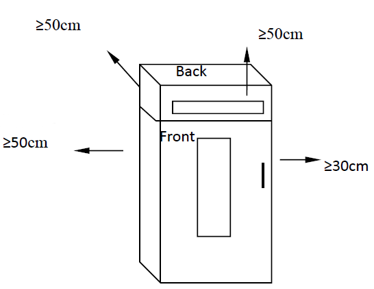
Figure 2
2. Power-on for Starting
2.1 Operating Panel
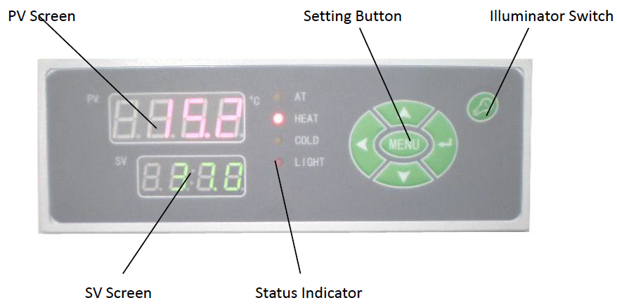
Figure 3
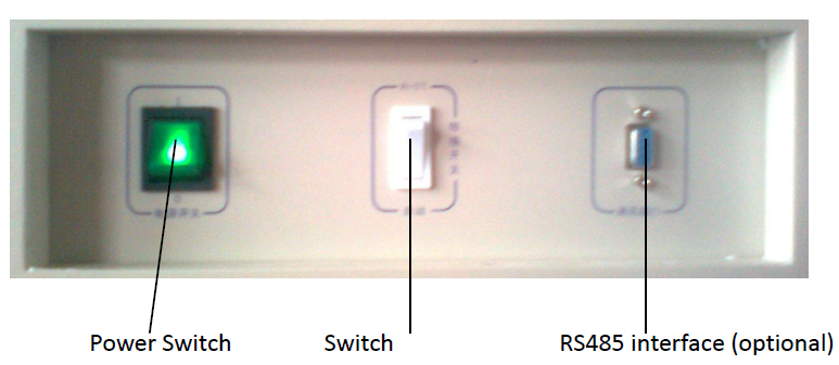
Figure 4
2.2 Turn on the power switch so that the motor runs; the temperature controller’s PV screen
displays the measured temperature and SV screen displays the set temperature. Then the
incubator will be in a state of running.
3. Setting of Temperature and Timing
3.1 Press down “MENU” key for the first digit on SV screen to flash.
3.2 Use “←” to select the flashing position of SV screen in cycling.
3.3 Use ↓” or “↑” to change the original figure in the flashing position of SV screen till coming to
the required temperature value.
3.4 Press again “MENU” key so that PV displays “Tl”; if SV screen displays “0”, it indicates that the timing function is not used (ex-factory state) and the product will run continuously.
3.5 Press “←” key, and use “↓” key or “↑” key to change the figure in the flashing position and the required timing value on SV screen. (Timing range: 1~9999min)
3.6 Press again “MENU” key twice to return the mode of running: PV screen displays the measured temperature and SV screen displays the set temperature.
4. Timing Function
4.1 When PV> (SV-1.0) (with the temperature up to the pre-set value), timing starts.
4.2 The decimal point on SV screen flickers, indicating the timed start in the countdown state.
4.3 In a normal running state, press “←”key so that SV screen displays the remaining time.
4.4 When the timing ends, all the output other than the fan will be automatically cut off; the buzzer continues to sound and SV screen displays “End”; press “MENU” key to remove “End” and then press ”Silence” key to silence.
4.5 If the timing ends, press hold “↑” key for about 4s to reset; if timing is required, set again.
4.6 Change of the timing: when the product is running in a timing state, it is allowed to change the time “T1”, while the previously pre-set time will be accumulatively “memorized” till the remaining time of the set time end. (If the new timing is less than the previously accumulated running time, immediately execute the timing end)
4.7 In case of switching on after a power cut during the use of timing, the timing shall be set again before it becomes effective.
5. Auto-tuning Function
In the running mode, press hold “↓” key for about 4s so that the temperature controller enters into auto-tuning and the auto-tuning AT lamp is lit. In the auto-tuning state, press hold “↓” key for about 4s so that the temperature controller will quit the auto-tuning and return to the running mode.
Since the parameter changed due to auto-turning function may influence the stability of temperature control, the unskilled person shall not use this function so as to avoid any exceptional running.
6. Use of Switch
6.1 (See Figure 1) When the set temperature is higher than the ambient temperature by 5℃, please select “RT+5℃”.
(With the cooler in the OFF state)
6.2 When the set temperature is close to the ambient temperature or lower than the ambient temperature by 5℃, please select “AUTO”.
(With the cooler in the RUN state)
7. Calibration of Temperature Control Accuracy
7.1 Place one 0.1℃ scaled mercurial thermometer (or digital temperature tester with the resolution of 0.1℃) inside the working chamber; the mercurial sensor of the thermometer should be in the geometric center of the effective space inside the working chamber
7.2 Select any point within the temperature control range for setting SV; when the measured PV equals to SV, keep the constant temperature for about 1~2 hours (which will depend on the specification of the product) and observe the mercurial thermometer: the difference between the actual measured temperature value and the measured PV displayed in the temperature control instrument should be less than or equal to ±0.5℃.
8. Increase of Temperature Control Accuracy
8.1 Correction of Bias between Measured Temperature and Actual Temperature inside Working Chamber.
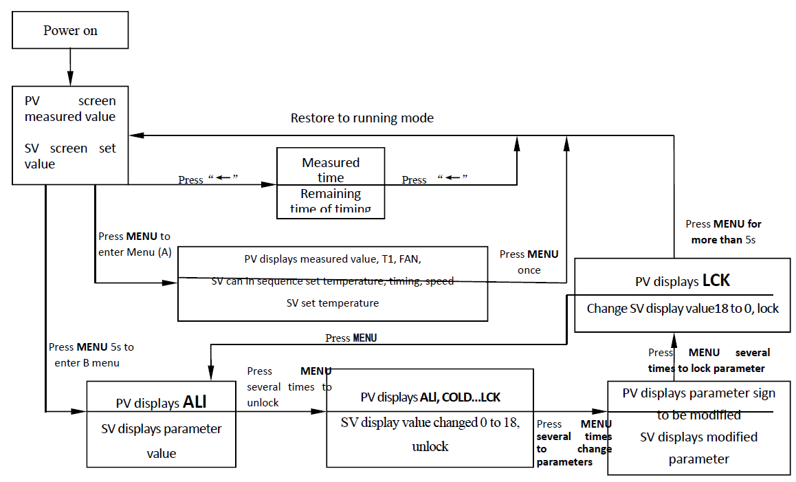
8.1.1 Press “MENU” key for more than 5s (to enter B Menu); when PV screen displays “ALl”, release, then press again Press MENU key several times to find the “L C K” prompt.
8.1.2 Press “↑” key so that SV screen displays 18 (i.e., unlock).
8.1.3 Press again “MENU” key several time to find “SC” prompt of the control parameter to be adjusted, press the functional key so that the control parameter is displayed as the required value.
SC = original SC value + (actual temperature – PV displayed value)
8.1.4 According to the above formula, calculate “SC” value for input (in case of failing to adjust correctly once, it can be repeated several times till complying with the standard).
8.1.5 If SC is already adjusted to the maximum (out of the range) and cannot be adjusted further, set “SC” to 0.
8.1.6 Press “MENU” key several times till PV screen displays “H L”; change “H L” to 1.000 and then return to the running mode.
8.1.7 In case of selecting, within the range of temperature measurement, two testing points, such as P1, P2 points, the gradient will be:
H L= (Glass P2- Glass P1) / (Instrument P2- Instrument P1)
(Make sure to keep three decimal points)
8.1.8 Where it is still incorrect after setting a new “H L” parameter, as per steps in 8.1.3, adjust again “SC” (repeatedly till complying with the standard).
8.1.9 If there is still a bias, correct repeatedly as per 8.1.3 and 8.1.4.
8.1.10 Upon completion of adjusting “H L” and “SC”, press “MENU” key to find “LCK” prompt, press “↓” key so that SV screen is displayed as 0 (lock), press “MENU” key for more than 5s to return to the running mode so that the instrument executes the revised parameter.
8.2 Control of Unstable Temperature (Excessive Overshooting
8.2.1 Refer to 8.1.1 for entering B menu.
8.2.2 Increase the parameter “P” (proportional band), by about 0.5 each time.
8.2.3 In the meanwhile, change the parameter “I”, by increasing 100s each time as well as change the parameter “D”, D = I/4, and heat up again for observation till the temperature overshooting complies with the requirement.
8.2.4 When the required temperature is relatively low, to reduce the temperature overshooting, the secondary setting can be applied.
(For instance: when the required temperature is 40℃, first set it to 38℃, wait for the temperature to become basically stable before setting to 40℃, so as to reduce or even stop any temperature overshooting.)
8.3 Call-out Sequence of Functions
9. Application of Optional “Overheating Protector”
Overheating Protector is an independent protection system. When the temperature is out of control due to the fault of the temperature controller and the temperature inside the working chamber is up the pre-set value of temperature limit on the overheating driver panel, the overheating protector will automatically cut off heating and alarm.
(As shown in Left Figure) when the temperature inside ℃ the working chamber is lower the set value, the protection system is cancelled and the instrument returns to running. It is repeated till the fault is eliminated.
10. Particular operating is as follows:
10.1 The set value of temperature limit should be ≥
(SV+AL) + (3~5) ℃
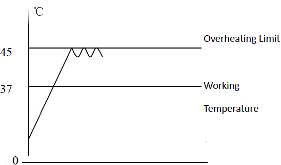
Figure 5
10.2 Use +/- button the overheating setting driver panel to set the required temperature limit For example: SV=37℃, AL=3
The set value of temperature limit should be set as 45℃.
Note: as per needs of the user, the product can be provided with the optional 30-section LC
/ND controller, which can be equipped with the optional RS 232c/485 communication interface,
Epson desktop or panel-embedded printer, etc.
4. Maintenance and Instructions
1. Conditions for Storage1.1 Ambient temperature: (-40~+55℃)
1.2 Relative humidity: ≤ 95% (25℃)
1.3 Air pressure: (50 ~ 106) KPa
1.4 Altitude: < 2000m
2. Method for Dehumidifying.
2.1 If the device stands idle for long, the power cable should be pulled out to avoid any human injury.
2.2 Regularly (generally once every quarter) run it for 5 hours as per application conditions so as to eliminate moisture on the electric parts and avoid any damage to the relevant parts.
2.3 Set the temperature at 40℃` and open the door every two hours to let out the moisture.
2.4 After handling, pull out the cable plug-in and wipe out the water from the case before storage.
3. Defrosting
3.1 The device runs at a low temperature (lower than the ambient temperature).
3.2 The cooling effect is not ideal (cooling slowly or causing a static error).
3.3 Every 15 days, “defrost”: set at 40℃ and keep the device running more than 3 hours.
3.4 After defrosting, reset the required parameter for running.
4. After use, turn off the main power supply and clean the water from inside the case.
5. Before using again or changing the technical requirement, check the temperature control accuracy. (Refer to III.3)
6. Except for such parameters as SV, SC, H L and L C K, that can be changed, other control parameters shall be adjusted subject to the consent of our Service Center or by the professional persons.
5. Appendixes
1. Technical SpecificationsThe product is manufactured as per enterprise standard Q/TIWY 11.
1.1 Biochemical Incubator
| Sr. No. | Model Index | BICL-7905 |
| 1 | Power Supply | AC(220±22) V (50±1)Hz |
| 2 | Temperature control range | 0℃~ 60℃ |
| 3 | Temperature resolution | 0.1℃ |
| 4 | Constant temperature fluctuation | HT: ±0. 5℃ LT: ±1. 0℃ |
| 5 | Chamber size (mm) | 540×550×1000 |
| 6 | Outer size (mm) | 637×662×1480 |
| 7 | Shelf panel | Three pieces |
| 8 | Coolant | R12 / 134a |
| 9 | Input power (W) | 600 |
Table 1
2. Tables of Functional Parameters
2.1 A Menu: press “MENU” key to enter
| Parameter Name | Function | Setting Range | Ex-factory Setting |
| SV window flash | Temperature setting | -5~65 degrees | |
| T1 | Timing | 0~9999min | |
| FAN | Fan speed adjustment | Set L as low speed Set N as medium speed Set H as high speed |
Table 2
2.2 B Menu: press hold MENU key for 5s to enter
| Prompt | Name | Setting Range | Ex-factory Setting | Ex-factory value |
 1 /AL1 1 /AL1 | Upper allowance alarm setting | (-99.9~999.9) ℃ | When temperature > SV+AL value, buzzer sounds, cut off heating output, SV screen synchronically displays “set value / ―――― ”, press any key for silence. | |
 / COLD / COLD | Cooling control setting | (-99.9~999.9) ℃ | When temperature > SV+CL value, COLD lit, cooling contact connected to start compressor. | |
 / SEC / SEC | Cooling start delay | (1~60) s | When actual temperature > (SV+CL), temperature controller, vide SEC delay, triggers cooling signal, cooling delays, COLD lamp flickers. | |
 / SC / SC | Display value Error correction | (-20~20) ℃ | Measure actual temperature inside for comparison with PV displayed temperature to correct display error | |
 / ATU / ATU | Auto-tuning command | 0, 1 | 0: OFF, 1: ON. Auto-tuning of one group of PID parameters. | Not recommended |
 / P / P | Proportional band | (0~100) ℃ | Heating proportion control, the higher P, the lower the system gains; reduction of P can increase system control accuracy and eliminate static error. | |
 / I / I | Integration time (re-adjusting time) | (1~4320) s | Constant of integration time; the bigger I, the weaker the integration and the system is stable. | |
 /d /d | Differential time (pre-adjusting time overshooting) | (0~1200) s | Constant of differential time; the bigger d, the stronger the differential is, and able to overcome over-tuning; generally d takes (1/4) times of I. | |
 / T / T | Heating period | (1~60) s | SCR output is generally (2~3)s, for the device with higher residual power, T is tuned higher to reduce the static error of PID. | |
| HL/HL | Gradient | 0.500~1.500 | Ensure consistent accuracy of temperature control in entire range | |
| ADDr | Mailing Address | |||
 / LCK / LCK | Password lock | 0, 18 | 18: unlock, 0: lockup. |
Table 3
※ All have been strictly tested before dispatching from the factory and shall not be corrected when the technical indexes meet the requirement and the running is normal.
3. Troubleshooting
| Faults | Possible causes | Action |
| Without power upon switching on (Indicator not lit) | Power socket is inactive or in poor contact | Repair |
| Power cable is broken or not properly plugged-in | Repair, re-plug-in | |
| Power switch is damaged (or not on) | Replace, turn on the power switch | |
| Fuse burnt out | If burning out again upon connection after change, check if motor and other parts are in short-circuit (damaged motor will smell, wire coil turns black) or case connected (insulation resistance as 0), repair before starting | |
| Instrument no display | Wire off or instrument burnt out | Connect again or change instrument |
| Instrument displays“- - - -” | Sensor damaged or wire broken (off) | Repair or change Pt100 (100Ω, 0.3Ω/℃ at 0℃) |
| Temperature out of control range | Use proper temperature value as specified | |
| No cooling | Switch not in proper position | Set to proper position |
| Compressor damaged or pipe blocked or coolant leakage | Change, clear, add coolant | |
| Compressor overheating protector actuated | Restore naturally when compressor temperature drops | |
| Compressor protector burnt out (with burning smell) | Change protector | |
| Temperature out of control AL1 indicator lit | AL1 set as 0 or incorrectly | Re-set |
| Two-way SCR breakdown | Change (Model: BTA16) | |
| Temperature controller damaged | Change temperature controller | |
| Temperature fails to rise | Temperature controller damaged(inactive, HEAT lamp not lit) | Change temperature controller |
| HEAT lamp lit | Change 3041/3061 trigger or BTA16 SCR | |
| HEAT lamp lit, two-way SCR not connected | Change two-way SCR (Model: BTA16) | |
| Timing used, temperature rises and falls | Keep T1≠0 | |
| Big error in temperature control or static error | Fan damaged (without running) | Change fan |
| Pt100 in poor contact, resistance increasing | Connect again | |
| Parameter (HL, SC) incorrectly set | Re-set | |
| PID and other parameters not properly set | Re-adjust the parameter | |
| Condenser frosts excessively, low cooling power | Heat up for defrosting (set 40℃, run for more than 3 hours) | |
| Fan sound abnormally or has a big noise (>70dB(A)) | Fan damaged or compressor fan damaged | Change the fan |
| Rubbed rear duct board or blade damaged | Repair (washer), adjust spacing |
Table 4
4. Wiring Principle Diagram
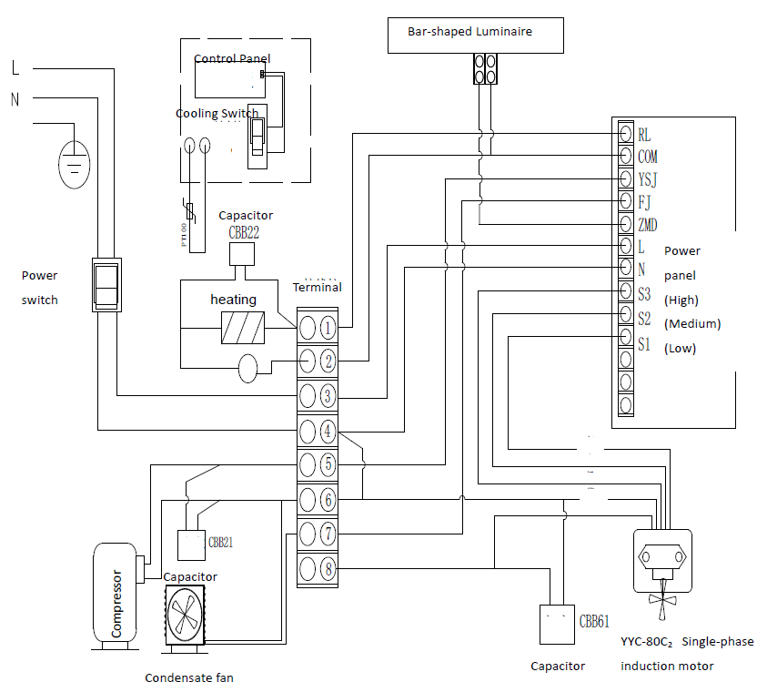
Figure 6
Packing List
| Sr. No. | Type | Description | Unit | Qty | Remarks |
| 1 | Document | User’s Book | Copy | 1 | |
| 2 | Document | Packing List | Copy | 1 | |
| 3 | Accessory | Shelf panel | Pc | 2 | |
| 4 | Accessory | Shelf strip | Pair | 2 | |
| 5 | Accessory | Water pan | Pc | 1 |
Packed by: 2 Inspected by: 1