Get Quote ▼
Meters Petroleum Equipment BPTL-303
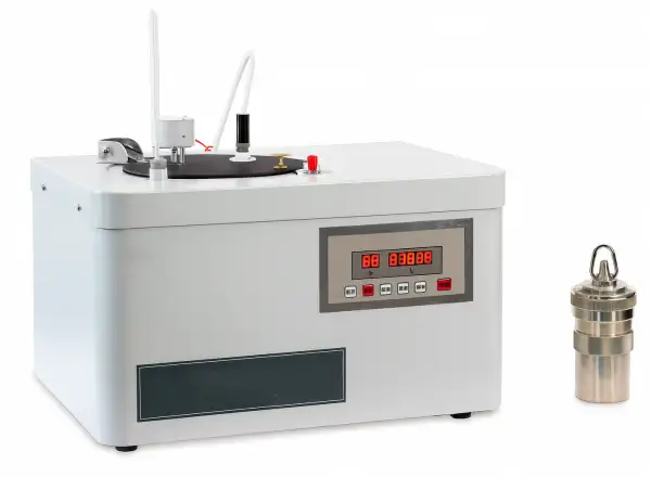
- The instrument is suitable to determine calorific value of combustible materials such as petroleum products without water (gasoline, jet fuels, diesel oil and fuel oils, etc.), coal, coke and paraffin, etc. This instrument adopts sealed oxygen bomb. The whole structure adopts stainless steel material. The inner water cylinder is composed of stainless steel sheet.The cross section is pyriform and the capacity is 3kg. The external water jacket is double layer container. It filled with water when doing determination.It make the water temperature in the cylinder uniform by water jacket stirrer and form the constant temperature environment meeting the requirements of test.
 Get Quote
Specifications
| Model | BPTL-303 |
| Heat capacity | 14400 J/K ~ 14500 J/K |
| Pressure endurance of oxygen bomb | 20 MPa |
| Temperature measurement range | 10 °C ~ 35 °C |
| Repeatability | ≤0.2% (Grade C) |
| Resolution | 0.001 K |
| Measurement accuracy | ≤ 60 J/g |
| Data saved | 31 pieces |
| Relative humidity | ≤ 85% |
| Power supply | AC(220±10%)V, 50Hz |
| Total power consumption | ≤150W |
| Dimension | 600x460x430 mm |
| Optional accessory | Pellet press machine |
Features
Applications
Operating Manuals
 Download Manual (PDF)
1. Instrument characteristics and scope
2. Main technical specification and parameters
3. Instrument structure
4. Operation methods
5. Operation procedure and calculation methods
6. Full set and technical documents
Appendix 1: Oxygen Bomb Diagram
Appendix 2: Absolute temperature
1. Instrument characteristics and scope
The instrument is designed and made as per the national standard "Test Methods for Calorific Value of coal", "Test Methods for Calorific Value of Petroleum Products" and "Oxygen Bomb Calorimeter".
The heat capacity of the instrument is 14000 J/K~15000 J/K, and it is suitable to determine calorific value of combustible materials such as petroleum products without water (gasoline, jet fuels, diesel oil and fuel oils, etc.), coal, coke and paraffin, etc.
Calorific value is expressed as follows: the heat produced by burning a unit of sample in the oxygen bomb containing excessive oxygen is the calorific value of sample (it is expressed as J/g or kJ/kg).
Burn a certain quantity of standard benzoic acid in the oxygen bomb and measure the temperature change of calorimeter system caused by the heat coming form the benzoic acid to determine the heat capacity of calorimeter. The heat (J) required for raising the calorimeter system 1 K is equal to the heat capacity of the calorimeter (J/K).
Note: The K in the words "Heat Capacity 14400 J/K~14500 J/K" is symbol of absolute temperature, please refer to appendix 2 for details.
2. Main technical specification and parameters
1. Heat capacity: 14000 J/K~15000 J/K;
2. Resolution: 0.001 K;
3. Measurement accuracy: ≤60J/g;
4. Temperature measurement range: (10~35)°C
5. Repeatability error: ≤0.2% (Grade C);
6. Pressure endured by oxygen bomb: 20 MPa;
7. Ambient temperature: (15~28) °C, the temperature fluctuation should not be more than 1 °C during a test;
8. Data saved: 60 pieces;
9. Relative humidity: ≤85%;
10. Power supply: AC 220V±5%, 50 Hz;
11. Total power consumption: ≤150W;
12.Dimension: 600㎜x460㎜x430㎜
3. Instrument structure
The structure of the instrument is shown as Fig.1.

Figure 1
(1) Thermometer (2) Stirring motor (3) Temperature sensor
(4) Handle (5) Controlling panel (6) Oxygen bomb
1. Self-sealed oxygen bomb
In order to protect the oxygen bomb from acid corrosion, the oxygen bomb is made of stainless steel ICrI8Ni9Ti. The oxygen bomb is composed of three parts: a 300 ml bomb cylinder, a cover and a ring for connecting cover to bomb cylinder. The inner diameter of bomb cylinder is 58 mm, its depth is 103 mm, and its thickness is 1/10 of inner diameter. The bottom and cover is a littler thicker, and its strength can withhold the largest pressure produced by burning solid materials (60~70 atmosphere pressure), and withhold larger pressure produced by burning liquid fuels.
The oxygen bomb adopts a rubber ring to seal it automatically. When the oxygen in the oxygen bomb reaches to a certain pressure, the rubber ring will tightly connect to bomb cylinder and bomb cover by the pressure. This will tightly seal the bomb cylinder and bomb cover. The larger the pressure difference is, the better the seal performance is. The gas valve in the middle will be tightly sealed by pressure. The oxygen will enter into oxygen bomb from the bolt of gas valve in the middle, so that it will not press the sample directly and can protect seal system at the top of oxygen bomb during ignition. The instrument has characteristics of convenience, reasonable and reliable structure, and long useful periods.
2. Water jacket (outer bucket)
The water jacket is a two layers container. The container is full of water during test. The temperature in the bucket is even when it is stirred by a water jacket stirrer to form a constant temperature environment. The water bucket is placed on an insulated holder, which has three points, in the water jackets.
The instrument cover has holes for inserting temperature sensor, and ignition wire. There is a polished metal plate lined under the cover.
3. Water bucket (inner bucket)
The bucket is made of stainless steel plate. After placing the oxygen bomb into the water bucket, please add water into the water bucket to submerge the oxygen bomb. But there should be about 250~500 ml space from the water surface to the upper edge of the inner bucket. The bucket can hold 3000 g water. There is an electric stirrer in the water bucket.
4. Stirrer
The stirrer is driven by a synchronous motor. Its stirring speed is 500 RPM and the stirring speed is even. Due to movement of stirrer, the heat produced by burning sample will be even in the calorimeter system. The motor and stirrer are connected by insulated plate to avoid the heat produced by electric motor affecting the measurement accuracy.
The stirrer in the outer bucket is a manual stirrer. The temperature of outer bucket can be even by pulling it up and down for many times. So it is used to provide a constant temperature environment.
5. Glass thermometer
The scale range of thermometer is 0°C~50 °C, and the smallest division is 0.1 °C. It is used to measure the water temperature in the water jacket.
6. Ignition wire
Use 24 V alternated electricity to ignite the ignition wire. The ignition wire is made of nickel-chrome wire, the diameter of which is about 0.1 mm. When the current flows through the wire, the nickel-chrome wire will be heated to red and will be melted in a short time to ignite the sample.
7. Gas decompression device
The YQY-370 gas decompression device or SJT-10 gas decompression device is used to reduce oxygen pressure in the oxygen flask. It can keep oxygen pressure stable and fill enough oxygen into oxygen bomb. The decompression device is equipped with two pressure meters, and one is used to indicate the pressure in the oxygen flask and it can indicate 0 MPa~25 MPa. The other is used to indicate pressure in the oxygen bomb, and it can indicate 0 MPa~6 MPa. There is a decompression valve between the two pressure meters. The pressure meters should be checked by National Department at least once a year to ensure their readings are correct and the safety of users. It is forbidden to add lubricating oils to the connection parts. If required, you can only spread some glycerin on them. Do not spread too much on them. If any one part is polluted by oils, you should clean it using alcohol or gasoline and dry it using wind.
8. Pellet press machine (optional part)
It is a pellet press machine of spiral lever type, and it can make coal cake or benzoic acid cake, the diameter of which is about 10 mm. The pressure mold and rod are made of steel, and their surface is smooth and easy to clean. When pressing sample, the mold are supported by movable shim. When the sample is complete, you can move the shim aside and take out of mold and sample. There is a bolt hole on the soleplate of pellet press machine to fasten the machine on the desk. If it is not be used, you should spread anti-rust grease on the corrodible parts.
9. Introduction of the controlling panel (see Fig.2)
Adopting a high performance temperature measurement system, which takes the micro-controller as the basis, the instrument has characteristics of high temperature measurement accuracy and fine stability. The measurement accuracy is 0.001 °C, and it is convenient to record temperature readings. The instrument can save all temperature data of the whole test into the memory during a test and read out the data repeatedly after the test. It completely replaces the Beckman thermometer used before. There are Power, Stir, Data, End, Ignite, and Reset, total six switches and a digital tube of seven digits on the panel of controller, and they are used for operation and temperature display during the whole test. The two numbers at the left indicates the temperature measurement times and the five numbers at right indicates the real temperature. The temperature measurement range is 10 °C~35 °C.
")
Figure 2
4. Operation methods
1. If you do not press the Ignite button after turning on the instrument, it will indicate 100 pieces of temperature data automatically. The measurement times will increase from 00 to 99 and change every half minute with alarm of buzzer. Press the End button or the Reset button at this time, the measurement times will be zeroed.
2. Press the Ignite button, and the 24 V alternated voltage will be imposed on the ignition wire. Then the ignition wire will melt and it will ignite the sample in the crucible. At the same time, the measurement times will be zeroed. Then the instrument will record temperature every half minute until it gets 60 pieces of measurement data. When getting 60 pieces of data, the temperature measurement times will be zeroed.
3. When the sample is burning, the temperature of inner bucket begins to rise up. After rise to the top, it begins to decrease. When the decreasing tendency of temperature is obvious, you can press the End button. Then press the Data button, the temperature data from 00, 01, 02 to the number when you press the End button can be indicated on the digital tube one by one. The user can record and calculate them or compare it to the temperature data recorded by the user in real time (Note: the data recorded by the computer is the temperature when the buzzer makes a sound) and calculate ΔT or calorific value of sample. When you press the Data button once, one of the saved temperature and temperature measurement times will be indicated. So it is convenient for the user to browse the temperature record.
Note: the Ignite button could not be used when reading out the data. If you want to make measurement again, you should press the End button to let the instrument back to temperature measurement state at first.
4. You can do the test again after you press the Reset button.
5. If you turn off the power supply, the temperature data saved will be cleared automatically.
5. Operation procedure and calculation methods
1. Preparation
(1) Carefully read Operation Manual before use.
(2) Carefully read GB/T 213 "Test Methods for Calorific Value of Coal" or GB/T384 "Test Methods for Calorific Value of Petroleum Products" and Calibration and Inspection Regulation of People's Republic of China JJG 672 "Oxygen Bomb Calorimeter" to acquaint and familiar with regulations, test methods, test procedures and test requirements stated in the standard and inspection regulation.
(3) Check the working state of the instrument to ensure it is in accord with working environment and working condition stated in the Operation Manual.
(4) Check the outer shell of the instrument to make sure it is fine grounded.
2. Solvent and material
(1) Benzoic acid: Grade two or higher standard heat measurement substance. It should be a standard substance issued by National Calibration Department, and have a standard substance certificate.
(2) Ignition wire: It is a piece of nickel-chrome wire, the diameter of which is about 0.1 mm. its length is 80mm~100 mm. Then place 10~15 piece of ignition wires on the balance and weigh them, and calculate the average weight of these ignition wires.
(3) Oxygen: At least 99.5% purity, electrolytic oxygen is not allowed to be used; The pressure is sufficient to charge the oxygen bomb to 3.0MPa.
3. Operation procedure
(1) Fill the outer bucket with water and let the temperature of outer bucket to be even using manual stirrer before test.
(2) Check the oxygen bomb
The oxygen bomb has undergone strict quality inspection before leaving the factory, but users must also conduct the following inspections before each test:
a) Check whether the air inlet is unobstructed;
b) Check whether the two electrode rods are loose and whether the circular fire baffle is fastened;
c) Check whether the crucible support is well fixed;
d) Check if there are foreign objects on the threads, sealing rings of the oxygen bomb body and oxygen bomb sealing cover;
e) Check whether there is any air leakage when the entire projectile is immersed in water after oxygenation;
f) Check where there is any damage to the appearance, etc.
(3) Weigh 1 g benzoic acid(about 2 pieces) to the crucible, nearest to 0.0002 g.
(4) Fix the crucible on the crucible holder and fix two ends of ignition wire on the two conductive poles. Let the ignition wire just touch the benzoic acid.
Note:
a) The ignition wire should not contact with the crucible to avoid bypassing the ignition current and causing ignition failure.
b) If it is a powdered coal sample, in order to obtain better test results, it's recommended to purchase our company's pellet press machine to press the sample into a cake shape before testing.
c) For powdered coal samples, the ignition wire should not be inserted into the coal and should be bent into an arc shape as close as possible to the surface of the coal sample.
Then add 10 ml distilled water into the oxygen bomb and screw on the cover of oxygen bomb tightly. Then fill oxygen into oxygen bomb until the pressure in the oxygen bomb is 2.8 MPa~3.0 MPa through oxygen pipe. Put the oxygen bomb filled with oxygen into the water to check for air leakage. If no bubbles are visible, it indicates that the oxygen bomb is not leaking.
Note:
a) It is strictly prohibited to short-circuit the two electrodes with a fire baffle;
b) Before installing the ignition wire each time, please remove any remaining ignition wires or other foreign objects from the electrode rod and wire pressing ring;
c) Prohibit overpressure oxygenation - normal range is 2.8MPa~3.0MPa, oxygenation time remains relatively consistent - about 30 seconds~45 seconds;
d) The oxygen bomb cover should not be screwed too tightly. After screwing it in place, a slight amount of force can be applied, whichever is air tight.
(5) Place the oxygen bomb on the oxygen bomb seat in the inner bucket, and add about 3000 g (nearest to 0.5 g) distilled water (its temperature is about 0.2~0.5 °C lower than outer bucket) into the inner bucket. The water surface should be at about 2/3 of the screw cap of oxygen inlet valve of the oxygen bomb. The quantity of water used at each time should be equal.
(6) Connect ignition connection wire and all other wires on the controlling case. Close the instrument cover and insert the sensor into inner bucket. Turn on the Power switch and the Stir switch, and then the instrument will show the temperature of inner bucket and the buzzer will alarm every half minute.
(7) If the temperature raising rate is even, record the indicated temperature when the buzzer alarms. When it records the tenth temperature data, press the Ignite button at the same time and the measurement times will be zeroed automatically. Then it will save temperature data every half minute until you get 31 pieces of temperature data. Press the End button to end the test (if the temperature reaches to the highest, but the number of temperature you record is less than 10 times, you should record several pieces of temperature manually).
(8) Stop stirring and take out of sensor. Open the instrument cover (Note: please take out of sensor at first, and then open the instrument cover) and take out of inner bucket and oxygen bomb. Discharge the oxygen in the oxygen bomb using a discharging valve. Open the oxygen bomb and check the inner of the oxygen bomb. If the sample is completely burned, the test data is valid, take out of ignition wire, which is not been used, and weigh it.
If the sample is not completely burned, discard the test data.
(9) Clean the oxygen bomb and crucible by distilled water and collect the liquid in to a 150~200 ml beaker.
(10) Cover the beaker containing the liquid, and heat it to boil for 5 minutes. Then add 2 drops
of phenolphthalein indication solvent and titrate it by 0.1 N sodium hydroxide solution and record the quantity of sodium hydroxide solution consumed.
If there is residual carbon in the crucible or oxygen bomb, please discard the test data.
4. Calculation equation of heat capacity (J/K)
 Place the oxygen bomb on the oxygen bomb seat in the inner bucket")
Where:E - Heat capacity of calorimeter, J/K
Q1 - Calorific value of benzoic acid, J/g
M1 - Weight of benzoic acid, g
Q2 - Calorific value of ignition wire, J/g
M2 - Weight of ignition wire, g
V - The volume of sodium hydroxide used, ml
Q3 - Titration correction for heat of nitric acid (the heat of 0.1 mol nitric acid is 5.9 J), J/ml;
ΔT - The temperature increase of calorimeter system after correction, °C; The calculation method is as follows:
ΔT = (tn - t0) + Δθ
Where: t0 and tn - the initial temperature and finial temperature of main period, °C
Δθ - the modified value of heat exchange between calorimeter system and environment, °C;
The calculation methods (Regnault-Pfaundler method) are as follows:
 Place the oxygen bomb on the oxygen bomb seat in the inner bucket")
Where:
V0 and Vn --- the temperature change rate in the initial period and final period, °C/30 s
θ0 and θn --- the average temperature in the initial period and finial period, °C
n --- Times to record temperatures in the main period
t1 --- the temperature readings in sequence in the main period
5. The calculation equation of calorific value of sample (J/g)
 Place the oxygen bomb on the oxygen bomb seat in the inner bucket")
Where:
ΣGd --- the total heat produced by the additive, J
G - Weight of sample, g
Other signs are the same as that in the equations mentioned above.
VI. Precautions and maintenance
1. Precautions
(1) The instrument should be placed in a single room without any sunshine. The workbench should be flat and the temperature of the environment should be at (15~28) °C. In order to ensure the measurement accuracy, the temperature change in the room should not be more than ±5 °C during each test. There should not have any heat source or air draft in the room.
(2) The calorific substance should be grade two or higher, and it has been checked by calibration department and marked with calorific value.
(3) The oxygen used in the oxygen bomb should be industrial oxygen, the purity of which is 99.5%. It is forbidden to use electrolysis oxygen.
(4) The instrument has been equipped with Ni-Cr ignition wire before leaving the factory.
(5) Keep the surface of the instrument clean and dry. Do not let the water flow into the instrument, or it will damage the circuit board. Especially, do not add two much water in the outer bucket to avoid any damage to the circuit board caused by water flowing out of outer bucket during stirring.
2. Maintenance
A. Maintenance of oxygen bombs
(1) Before each formal test, it is necessary to immerse the oxygen bomb with sufficient air (not less than 3.0MPa) in water for several minutes to observe whether the sealing performance of the oxygen bomb is good and ensure the reliability of the test results.
(2) After each test, it is necessary to wipe and rinse all components of the oxygen bomb with distilled water to remove dirt and debris, and dry them with a dedicated towel to keep the inside and outside of the bomb clean, free from dirt, and residue from previous tests.
Note: It is particularly important to point out that the small insulation pad in the oxygen bomb assembly must be cleaned thoroughly and there must be no residue of any sample!
(3) If oxygen bomb leakage is found or the sealing ring is damaged, replace it with a spare sealing ring. Otherwise, it cannot be used again.
(4) If the thread of the oxygen bomb is found to be slipping, it is prohibited to continue using the oxygen bomb.
(5) Carry out 20 MPa hydraulic pressure test regularly, at least once a year.
(6) After use, the sample crucible should be cleaned thoroughly and it is recommended to bake at high temperature on an electric furnace for 3-5 minutes until completely dry.
(7) Be careful when removing and placing oxygen bombs from the inner cylinder to prevent damage to other components or devices due to collisions or falls.
(8) When oxygen bombs are not used for a long time, they should be placed in a dry and ventilated place and properly stored while ensuring that the inside and outside of the bomb body are clean, free of dirt, dirt, and residue from previous tests.
B. Maintenance of oxygenation equipment and related components
(1) The oxygen used for testing must meet the requirements specified in the GB/T 213-2008 Coal Calorific Value Determination Method: at least 99.5% purity, and electrolytic oxygen is not allowed to be used; The pressure is sufficient to charge the oxygen bomb to 3.0MPa.
(2)After each oxygen filling, the main oxygen valve shall be closed and the oxygen in the gas circuit shall be released. The method is: close the valve of the Oxygen cylinder, fill the oxygen with an oxygen bomb until the oxygen pressure is zero, and then release the residual oxygen in the oxygen bomb.
(3) The place where the Oxygen cylinder is placed shall comply with the relevant national regulations, and fireworks are strictly prohibited.
(4) It is strictly prohibited to bend the oxygen filling catheter and maintain its integrity.
(5) Regularly check whether the pressure gauge on the oxygen charger and the low-pressure gauge on the pressure reducing valve indicate the same value.
(6) It's prohibited to use lubricating oil for each connection part in the entire oxygen charging circuit. If necessary, only glycerol can be used, and the application amount should not be too much. If any connection part is contaminated with oil, it must be washed with gasoline or alcohol and air dried.
(7) Clean the oil on the accessories before using the oxygen decompression device to avoid burst when you fill oxygen. Do pressure test for oxygen decompression device regularly, at least once a year.
(8) After the oxygen charging is completed, please slowly release the handle of the oxygen charger.
Note: The oxygen charger is an optional component.
C. Maintenance of the host and other components
(1) After using the instrument, the surface should be kept clean and dry to prevent corrosion. When not in use for a long time, all water in the instrument's water cylinder should be drained, and the wiping area should be wiped clean and placed in a dry place.
(2) Add lubricant oil to the rotation shaft of stirring motor every half year or year (it is decided by the using frequency).
Note: When the room temperature is lower than 0 °C, please exhaust water bath in the water bath to avoid any damage to the instrument caused by freezing.
Warning: If there is any trouble appears, please cut off the power supply immediately. Then ask a professional to check and repair it. You can use it only after the problem is solved to avoid any accidents.
6. Full set and technical documents
1. Full set
No | Name | Unit | Quantity | Remark |
1 | Main unit of calorimeter (including oxygen bomb, water jacket, bucket, stirrer and controller of calorimeter) | Set | 1 | |
2 | Pellet press machine | Set | 1 | Optional part |
3 | Holder of bomb head | Set | 1 | |
4 | Seat of oxygen bomb | Set | 1 | |
5 | Temperature sensor | Piece | 1 | |
6 | Thermometer (0~50 °C) | Piece | 1 | |
7 | Stopper for thermometer (silica gel stopper 2#) | Piece | 1 | |
8 | Ignition wire (Φ0.1 nickel-chrome wire) | Meter | 10 | |
9 | Crucible | Piece | 2 | |
10 | Discharging valve | Piece | 1 | |
11 | Oxygen decompression device | Piece | 1 | |
12 | Oxygenator | Pair | 1 | |
13 | "O" seal ring (Φ20x2.4 mm) | Piece | 5 | |
14 | "O" seal ring (Φ8x1.9 mm) | Piece | 5 | |
15 | "O" seal ring (Φ6x1.9 mm) | Piece | 5 | |
16 | Seal ring (large "O" ring) | Piece | 2 | |
17 | Ignition connection wire | Piece | 1 | |
18 | Siphon | Piece | 1 | |
19 | Benzoic acid | Piece | 10 | |
20 | Stopping ring for thermometer (1#) | Piece | 4 | |
21 | Oxygen bomb hook | Piece | 1 |
Table 1
2. Technical documents
(1) Operation Manual 1 piece
(2) Repair Guarantee 1 piece
(3) Quality Certificate 1 piece
Appendix 1: Oxygen Bomb Diagram

Figure 3
1. Valve handle 2. O type seal ring 3. Fixing ring for seal ring
4. Seal ring 5. Bomb nut 6. Hexagon nut
7. Conductive sleeve 8. Conductive pole 9. Bomb cylinder
10. Ignition wire 11. Oxygen bomb seat 12. Handle ring
13. O type seal ring 14. Oxygen bomb top nut 15. Bomb lid
16. Large insulation gasket 17. Clamp spring 18. Insulation pipe
19. Small insulation gasket 20. Gas valve 21. Crucible holder 22. Crucible
Appendix 2: Absolute temperature
Thermodynamic temperature is also called as Kelvin temperature or absolute temperature, and its symbol is K. The temperature at absolute zero is defined as 0 K The three-phase point of water, which is expressed as the temperature when the water is in the liquid, solid, and gas state at the same time, is defined as 273.16 K.
The temperature when the water freezes at standard atmospheric pressure is at Celsius temperature of 0 °C, or Fahrenheit temperature of 32 OF. The temperature is equal to thermodynamic temperature of 273.16 K.
The relationship between absolute temperature and Celsius temperature:
Absolute temperature T≈ Celsius temperature t +273 degree;
Absolute temperature 0 degree≈ Celsius temperature of 273 degree.