


Air Jacketed Incubator BIAJ-105
- Sea, Air, Door to Door Shipping
- 1 Year Warranty
- US & European Standards
Natural air convection method and gentle air circulation provide excellent temperature homogeneity. Glass observation window with air tight lock and silicon rubber sealing prevents unwanted loss of heat. Stainless steel interiors with heating elements on all six sides provide uniform heating even if load is high. This series is designed to reduce sample contamination and provide a stable environment for growth and maintenance of cell cultures.
- Stainless steel inner chamber with semicircular transition and adjustable shelves
- Easy to use interface
- LCD display with multiple displays of data and timer function
- Door having tempered glass observation window with adjustable air-tight lock
Specification
Features
Applications
| Capacity | 230 L |
| Temperature Range | RT+5-80°C |
| Ambient Temperature | 5-40°C |
| Temperature Accuracy | ±0.2°C |
| Temperature Uniformity | ±0.5°C |
| Temperature Resolution | 0.1/±0.2°C |
| Timer Range | 1-9999 min |
| Load per shelf | 15 kg |
| Internal Dimension | 600Wx500Dx750H mm |
| Exterior Dimension | 730Wx670Dx1220H mm |
| Package Size | 900x800x1300 mm |
| Shelves | 2 |
| Weight | 94/120 kg |
| Power | 700 W |
| Power Supply | 220V, 50Hz |
- Stainless steel inner chamber with semicircular transition and adjustable shelves
- Easy to use interface
- LCD display with multiple displays of data and timer function
- Door having tempered glass observation window with adjustable air-tight lock
- Silicon rubber sealing to prevent heat loss
- Over temperature protection
- Overheat thermostat with auto power shutdown function
Cell Culturing, Tissue culturing, Tissue Engineering, Vitro fertilization, Mammalian cell research, Oncology studies.
Operating Manual for BIAJ-105
1. Safety warning before use
2. Main features of product
3. Main features of product
4. Instrument operation and display instructions
5. Instrument wiring diagram
6. General faults and troubleshooting methods
1. Safety warning before use
1.Do not store volatile, flammable or explosive materials in the equipment, otherwise it may cause explosion or fire.2.Do not place the equipment in a place that is wet, wet or may splash water, otherwise it may lead to accidents such as leakage, short circuit or electric shock.
3.Non-professional technicians shall not disassemble, repair or modify the equipment, otherwise it may cause fire or electric shock accidents due to improper operation.
4.The equipment should be installed on a solid ground. If the ground is not solid enough or the installation site is not suitable, injuries may be caused by the equipment tipping over.
5.The equipment should be installed on a solid ground. If the ground is not solid enough or the installation site is not suitable, injuries may be caused by the equipment tipping over.
6.Before any repair or maintenance of the equipment, be sure to disconnect the power supply to prevent electric shock or personal injury.
7.Be sure to wear gloves when performing equipment repair or maintenance to prevent injury caused by touching edges or sharp corners.
8.If the equipment is found abnormal operation, immediately unplug the power plug, stop the operation of the equipment. Operation under abnormal conditions may cause electric shock or fire.
2. Main features of product
1. Unique vertical double duct circulation horizontal air supply, uniform temperature distribution in the working room.2. The 2.4 speed 3-speed fan can adjust the air volume required by the experiment according to the different experimental requirements of the user, and the standard high-light LED instrument running indicator.
3. Independent overtemperature protection system: When the temperature in the working room exceeds the alarm value set by the instrument, the heating main circuit is cut off to improve the safety of the product.
4. High precision digital display independent temperature limiter, set the studio limit temperature, to provide double security for the product. III. Product structure diagram and parameters.
3. Main features of product
| BIAJ-101 | BIAJ-102 | BIAJ-103 | BIAJ-104 | BIAJ-105 | ||
| Cycle Mode | Forced convection | |||||
| Function | Temp. range | RT+5-120℃ | ||||
| Temp. Resolution Ratio | 0.1℃ | |||||
| Temp. Motion | ±1℃ | |||||
| Temp. Uniformity | ±1.0℃ | |||||
| Structure | Inner Chamber | Mirror Stainless Steel | ||||
| Outer Shell | Cold rolling steel electrostatic spraying exterior | |||||
| Insulation layer | Compound silicate heat preservation board | |||||
| Heater | Stainless steel heater | |||||
| Power rating | 0.4kW | 0.5kW | 0.7kW | 1.1kW | 1.5kW | |
| Exhaust hole | φ28mmtop( with function of test hole) | |||||
| Timer | 0-9999min(with timing wait function) | |||||
| Sensor | pt100 | |||||
| Specification | Inner Chamber size(W*L*H)(mm) | 310*310*310 | 350*350*350 | 400*360*450 | 500*450*550 | 600*500*750 |
| Exterior size (W*L*H)(mm) | 460*510*695 | 500*550*735 | 550*550*840 | 636*680*915 | 730*680*1250 | |
| Packing size (W*L*H)(mm) | 550*585*845 | 590*625*885 | 640*635*985 | 740*725*1085 | 860*790*1400 | |
| Volume | 30L | 45L | 65L | 125L | 230L | |
| Shelf number | 6 | 7 | 9 | 13 | 17 | |
| Load per rack | 15kg | |||||
| Shelf space | 35mm | |||||
| Current rating | 220V/3.6A | 220V/5.5A | 220V/7.2A | 220V/10.5A | 220V/13.6A | |
| NW/GW (kg) | 33/37 | 37/43 | 44/49 | 60/66 | 94/120 | |
| Shelf | 2 | |||||
Table 1
4. Instrument operation and display instructions
1. Panel InstructionsThe panel indication
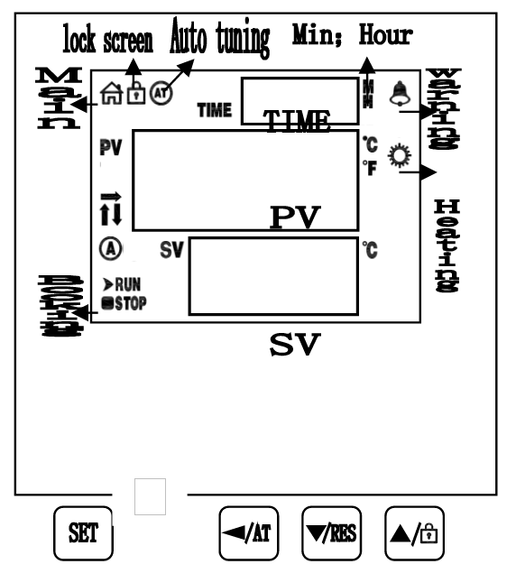
Figure 1
Key defines
1. 【Set】: Set key, in the main screen state, click this key to enter the temperature and time target value Setting state, long press this key for 3 seconds to enter the internal parameter Setting state.
2. 【 】: Shift / Auto-tuning, in the Setting state, click this key to change the Setting value.In the main screen state, long press this key for 6 seconds to temperature auto-tuning selection state.
3. 【 】: Decrease / rerun key. In the Setting state, click or long press this key to decrease the Setting value. In the main screen state, long press this key for 3 seconds to restart the run.
4. 【 】: Increase / lock screen key. In the Setting state, click or long press this key to increase the Setting value.In the main screen state, click this key to lock or unlock the screen.
PC-D9000 VA LCD indicator Defines
1. 【Main】indicator : In the normal working state (non-Setting state), the lamp will be on, otherwise it will be off.
2. 【Lock】indicator: It will be on when the screen is locked, otherwise it will be off.
3. 【AT】indicator:The lamp flashes during temperature self-adjustment and goes out instead.
4. 【Alarm】indicator: The lamp will be on when there is temperature deviation alarm or abnormal temperature measurement. It will flash when there is temperature deviation alarm. Under normal condition, it will be off.
5. 【Heating】indicator: The lamp will be on when there is heating output, otherwise it will be off.
6. 【A】indicator: The lamp will be flash in reservation timing, otherwise it will be off.
7. 【RUN/STOP】indicator: Only STOP lights up at the end of timing, and RUN lights up in other states.
8. 【↑/→/↓】indicator:It will flash when heating, constant temperature and cooling.
2. Operations and usages
1. Controller power on display
1)Type PC-D9000:PV displays 【P(K) – d9】, the SV displays the version number for about 3 seconds and then enters the normal display state.
2)Type PC-E9000:After all the display are on for about 3 seconds, PV area displays 【P(K) – E9】, SV displays version number for about 1 second and then enters the normal display state.
2. Reference and Setting of temperature and time
1) No-timing function:
In the main screen state, click the【Set】to enter the temperature Setting state, the PV area displays prompt SP, and the SV area displays the temperature Setting value, which can be modified to the required Setting value through the【shift】、【increase】、【decrease】, then click the【Set】to exit the Setting state, and the Setting value will be saved automatically.
2) Timing function:
In the main screen state, click the【Set】to enter the temperature Setting state, the PV area displays the prompt SP, the SV area displays the temperature Setting value, and the modification method is the same as above; then click the 【Set】 to enter the time Setting state, the PV area displays the prompt ST, TIME area displays the time Setting value; then click【Set】to exit the Setting state, and the Setting value will be saved automatically.
When the Setting time is "0", it means continuous operation. When the Setting time is not "0", before the timing starts, if the timing direction is count-down, the TIME area will display the timing time; if the timing is count-up, the TIME area will display "0". When the timing starts, "indicator" will flash.When the time is up, the operation will end. The TIME area will display End, and the buzzer will beep for EST seconds (see 7. Parameter TABLE-1). At this time, long press the 【decrease】for 3 seconds, the operation can be restarted.
Description: PC-D9000 type, "indicator" is "time unit";
PC-E9000 type, the "indicator" is "TIME displays decimal point of single digits."
3.Reservation function(see7.Parameter TABLE-6)
When an reservation time is Set, heating operation is prohibited.
1) PC-D9000 type: In reservation timing,A indicator flashes, and the count-down TIME area displays the reservation running time.
2) PC-E9000: In reservation timing,TIM indicator flashes, and the count-down TIME area displays the reservation running time.
4. Abnormal temperature measurement alarm
5. If the PV area displays "----", it means that the temperature sensor is faulty or the temperature exceeds the measuring range or the controller itself is faulty. The controller will automatically disconnect the heating output, the buzzer will sound continuously and the alarm light will be on. Please check the temperature sensor and its wiring carefully.
5.Deviation over temperature alarm (see 7. Parameter TABLE-1)
When the upper deviation over temperature alarm occurs in process, the buzzer beeps, the alarm light is continuously on, and the heating output is disconnected. When the lower deviation over temperature, the alarm will occur and flash. If the over temperature alarm is generated due to changing the temperature Setting value, the alarm light will be on, but the buzzer will not sound.
6. Lock screen function.
Three screen locking modes are provided. See [7. Parameter TABLE-1] for details.
Password unlocking: In the lock screen state, click the 【increase】, the input password prompt PA is displayed in PV area, and the password is displayed in SV area. After entering the correct password, click the【Set】to unlock.
7. When the buzzer sounds, press any keys to silence.
Auto-tuning system
When the temperature control effect is not ideal, the system can be auto-tuning. There will be a large overshoot in the process of auto-tuning. Please take this factor into consideration before system auto-tuning.
In the running state and the main screen state, long press the 【shift】for 6 seconds to enter the system auto-tuning selection state. The PV area displays the auto-tuning prompt AT, and the SV area displays "0". You can click the 【increase】 or 【decrease】 to select the display "1", and then click the 【Set】to enter the system auto-tuning state. The AT light flashes. After the auto-tuning is completed, the AT light stops flashing The controller will get a better set of PID parameters and save them automatically. In the process of system auto-tuning, long press the【shift】for 6 seconds to stop the auto-tuning program.
In the process of system auto-tuning, if there is an over temperature alarm of upper deviation, the alarm light will not be on and the buzzer will not sound, but the alarm relay will be automatically disconnected. In the process of system auto-tuning, the【Set】 is invalid.
VII. Seven The internal parameters of the temperature are seen and Set.
In the main screen state, long press the【Set】for 3 seconds, the password prompt LC will be displayed in PV area, and the password will be displayed in SV area. Modify the required password through【increase】、【decrease】 and 【shift】, and then click the 【Set】. If the password is incorrect, the instrument will automatically return to the main screen state. If the password is correct, enter the internal parameter setting state, and then click the【Set】to modify each parameter in turn. In this process, long press the【Set】for 3 seconds to exit this state, and the parameter value will be saved automatically. See the table below for details:
Description:
1) In the parameter TABLE, the temperature setting is referred to as SP,the temperature measurementis referred to as PV.
2)In the TABLE below, PT100, M=400.0℃, Type K, M =600.0℃
Parameter TABLE-1
| The Indicator | Parameter Name | Description of the parameter function | (Range) Initial value |
| Lc | Password. | Lc=3,parameter values can be viewed and modified | 0 |
| ALH | Upper Deviation Over-temperature Alarm | PV>SP+ALH, over-temperature alarm of upper deviation | (0~100.0℃) 20.0 |
| ALL | Lower Deviation Over-temperature Alarm | PV<SP-ALL,over-temperature alarm of upper deviation Description:ALL=0,the lower deviation alarm is invalid | (0~100.0℃) 0 |
| Pb | Temperature Measurement Deviation Correction | Used to correct errors in temperature measurement. Pb = Actual temperature-PV | (-50.0~50.0℃) 0 |
| PL | Temperature Measurement Slope Correction | It is commonly used to correct errors arising from high temperature measurement. PL = 1000 * (Actual temperature-PV)÷ PV Description: In Parameter【TABLE - 4】,En = 1 This feature is invalid. | (-999~999) 0 |
| ndT | Timing Mode | 0:No-timing; 1:Constant temperature timing; 2: Run timing. | (0~2) 1 |
| Tdn | Timing Direction. | 0:Count-up; 1:Count-down | (0~1) 0 |
| Hn | Time Unit. | 0:Minute; 1:Hour | (0~1) 0 |
| SPd | Constant Temperature Deviation | SP-SP d ≤PV≤SP+SP d, Enter a constant temperature state. | (0.1~50.0℃) 0.5 |
| EST | End Timing Prompt Time | When the timing is over, the buzzer will prompt the time. Note: EST = 9999, indicates a permanent prompt. | (0~9999s) 60 |
| EH | End Timing Constant Temperature Controller | 0: Turn off the heating output after timing; 1: Keep constant temperature controlling after timing | (0~1) 0 |
| LF | Lock Screen Function | 0: Lockless screen function; 1: Lock screen function, unlock without password. 2: Lock screen function, need password to unlocked. | (0~2) 0 |
| LdT | Lock Screen Delay | In the main screen state, if no key is pressed in the delay LDT time, the controller will automatically lock the screen. Description: LDT = 600, the delay screen locking function is invalid | (10~600s) 30 |
| PAd | Unlock Password | The password must be entered to unlock it. | (0~9999) 1 |
| Add | Mail Address | Local Address Description: PC-E9000 has no communication function. | (1~32) 1 |
Table 2
Argument TABLE -2.
| The Indicator | Parameter Name | Description of the parameter function | (Range) Initial value |
| Lc | Password | Lc=6,parameter values can be viewed and modified | 0 |
| dP | Demarcation Point | High and low temperature PID control demarcation point. When SP≤ DP, it is low temperature control, otherwise it is high temperature control. | (0~M℃) M |
| T | Control period | Heating control period. | (1~30s) 5 |
| P1 | Proportional Band 1 | The time proportion regulation in low temperature control. Description: P1 = 0, it is digit controlling. Note: when P1 = 0, it is position control. | (0~300.0℃) 35.0 |
| I1 | Integral time 1 | Integral regulation in low temperature control. | (1~2000s) 300 |
| d1 | Differential time 1 | Differential regulation in low temperature control. | (0~1000s) 200 |
| nP1 | Power Output 1 | Maximum power percentage of heating output at low temperature control. | (0~100%) 100 |
| nH1 | Heating Off Deviation 1 | In low temperature control, if PV ≥ SP + nh1, it will turn off the heating. Description: please use this parameter with caution! | (0~50.0℃) 50.0 |
| P2 | Proportional Band 2 | The time proportion regulation in high temperature control. Description: P2 = 0, it is digit controlling. Note: when P1 = 0, it is position control. | (0~300.0℃) 35.0 |
| I2 | Integral Time 2 | Integral regulation in high temperature control. | (1~2000s) 300 |
| d2 | Differential Time 2 | Differential regulation in high temperature control. | (0~1000s) 200 |
| nP2 | Power Output 2 | Maximum power percentage of heating output at high temperature control. | (0~100%) 100 |
| nH2 | Heating Off Deviation 2 | In high temperature control, if PV ≥ SP + nh2, it will turn off the heating. Description: please use this parameter with caution! | (0~50.0℃) 50.0 |
Table 3
Argument TABLE -3
| The Indicator | Parameter Name | Description of the parameter function | (Range) Initial value |
| Lc | Password. | Lc=9,parameter values can be viewed and modified | 0 |
| doT | Display Decimal point | 0: No decimal point for temperature measurement and set value; 1: The temperature measurement and the set value have 1 decimal point. | (0~1) 1 |
| oPn | The Door Control Function | 0:No use; 1:Use Note1 | (0~1) 0 |
| SPL | Minimum. Set value | The minimum value of the temperature setting. | (-50.0~20.0℃) 0 |
| SPH | Maximum Set value | The maximum value of the temperature setting. | (20.0~M℃) 300.0 |
| ouT | Heating. Output Mode | 0: normal state ; 1: The alarm relay output (normally opening point) is changed to heating output, and the original heating output is invalid. Note2 | (0~1) 0 |
| db | Nonsense Region | The nonsense region of the temperature measurement. | (0~5.0) 0.0 |
| ndo | Switch Output Mode | 0: At the end of timing; 1: Over-temperature alarm; 2: Enter the constant temperature state Note3 | (0~2) 1 |
| ndA | Temperature Alarm Mode | 0: Only the temperature deviation over-temperature alarm; 1: Temperature up and down deviation over-temperature alarm concurrently. | (0~1) 0 |
Table 4
Note 1: In order to avoid misjudgment, please select to turn off the open door judgment function for the equipment that does not need to open the door or the temperature drops quickly.
Note 2: When the ouT value changes from 0 to 1, the heating control T period automatically changes to 20 seconds and saves; when the ouT value changes from 1 to 0, the heating control T period automatically changes to 5 seconds and saves.This function is only applicable to PC-9x01 (driving solid-state SSR output) . It is forbidden to change the initial value of other types of instruments, otherwise the control will be abnormal!
Note 3:Only PC-D9201 (driving solid-state SSR with switch output) has this function. Switch output means that the normally opening point of switch relay is closed.
Argument TABLE -4.
| The Indicator | Parameter Name | Description of the parameter function | (Range) Initial value |
| Lc | Password. | Lc=12,parameter values can be viewed and modified. | 0 |
| En | Correction Enable | 0: disable multi-segment correction function; 1: Enable Note: when En = 1, 【parameter TABLE-1】 is invalid. | (0~1) 0 |
| U1 | Correction Point 1 | If PV≤U1,use E1 to correct the temperature slope. | (0-MMC)) M |
| E1 | Correction Point 1 | E1 = Actual temperature-PV | (Note4) 0 |
| U2 | Correction point 2 | If PV≤U2,use E2 to correct the temperature slope. | (U1-M-C)) M M |
| E2 | Correction point 2 | E2 = Actual temperature-PV | (Note4) 0 |
| U3 | Correction point 3 | If PV≤U3,use E1 to correct the temperature slope. | (U2-M-C)) M M |
| E3 | Correction point 3 | E3 = Actual temperature-PV | (For4) 0 |
Table 5
Note4:Temperature Unit is Celsius:-180.0~180.0;Temperature Unit is Fahrenheit:-180.0~324.0
Description: Before adopting this correction, Pb in 【parameter TABLE-1】 should be equal to 0, the measured value of temperature display should be equal to the corrected value + Pb
Argument TABLE -5.
| The Indicator | Name | Description of the parameter function | (Range) Initial value |
| Lc | Password | Lc=27,parameter values can be viewed and modified modified at Lc s27. | 0 |
| Fc | Temperature unit | 0: Celsius; 1: Fahrenheit. | Note5 |
Table 6
Note 5:Type PT100:(0~1) 0; K-type thermocouple: (0~0) 0
Argument TABLE -6
| The Indicator | Name | Description of the parameter function | (Range) Initial value |
| Lc | Password | Lc=81,parameter values can be viewed and modified | 0 |
| APT | Reservation Time | Set power-up time Description:APT = 0, this function is invalid. | (0~9999min) 0 |
Table 7
Argument TABLE -7
| The Indicator | Name | Description of the parameter function | (Range) Initial value |
| Lc | Password | Lc=567,parameter values can be viewed and modified | 0 |
| rST | Factory Reset | 0:Cancel; 1:Conform。 | (0~1) 0 |
Table 8
5. Instrument wiring diagram
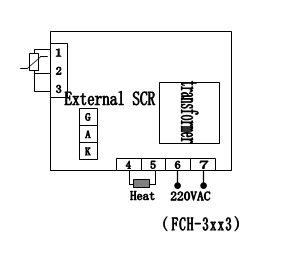
Figure 2
6. General faults and troubleshooting methods
| Phenomena | Causation | Treatment Method |
| 1.No power supply | a. poor plug contact or line broke | a. Connect the plug and line. |
| b. Fuse protector is broken. | b. Change the fuse protector. | |
| 2.No temperature rising inside container | a. Low setting temperature | a. Readjust and set temperature |
| b. Heater is broken. | b. Change the heater | |
| c.Temp. controller is broken | c. Change the temperature controller | |
| d. Temp. sensor is loose. | d. Screw up the sensor nut. | |
| e. Temp. sensor is broken | e. Change the temperature sensor. | |
| 3. No temperature rising alarm | a. Set temp. of Detached temp. limiter is low | a. Readjust the temperature 30℃ above setting temperature. |
| b. Detached temp. limiter sensor is broken. | b. Change the detached temperature limiter sensor | |
| 4. Temperature cannot reach the setting point. | a. Exhaust port is fully opened | a. Shut off the exhaust port. |
| B.The container is overfilled, no hot air convection. | b. Decrease amount of sample to improve convection condition. | |
| 5. The fan doesn’t work. | The fan motor is broken | Stop work and check electric capacity and motor |
| 6.Displaying------- | The sensor is broken | Change the sensor |
| 7.Display STOP | Time-up | Press the program key for 3s to start |
Table 9