


32x0.2mlx3 Gradient Thermal Cycler BTHC-110
- Sea, Air, Door to Door Shipping
- 1 Year Warranty
- US & European Standards
Engineered by finest quality and leading edge technology according to the advance technology and market norms under the direction of competent experts. Simple, intuitive programming, cost-efficient, fast setup and convenient to use makes it an ideal choice.
- The most advanced peltier-based semiconductor technology
- Highly performance universal power supply
- Large 5.7 inch high-definition LCD display
- Graphical user interface in English and Chinese
Specification
Features
Applications
| Sample Capacity | 3x(32x0.2 ml ) |
| Temperature Range | 0~100°C |
| Temperature Increment/Decrement | 0.1~10.0°C |
| Hold at 4°C | Forever |
| Max. ramp rate | 0.1°C~5°C |
| Max Heating Rate | 5°C / s |
| Max Cooling Rate | 4°C / s |
| Display Interface | LCD, 8',800x600, TFT |
| Display Resolution | 0.1°C |
| Uniformity | ≤±0.3°C |
| Accuracy | ≤±0.2°C |
| Gradient Temp Range | 30°C~100°C |
| Gradient Spread | 1~30°C |
| Hot Lid Temperature | 30°C~110°C |
| Height of hot Lid | Stepless Adjustable |
| Max.No.of Cycle | 100 |
| Program Storage | 10000+(USB Flash) |
| Max Program Steps | 30 |
| Communication | USB2.0 , LAN |
| Temp Control Mode | Block, tube |
| Time Increment/Decrement | 1 sec ~600 sec |
| Pause Function | Yes |
| Auto Data Protection | Yes |
| Dimension (WxDxH) | 270x390x255 mm |
| Power | 600 W |
| Weight | 9 kg |
| Power Supply | 85~264 V AC , 47~63 Hz |
- The most advanced peltier-based semiconductor technology
- Highly performance universal power supply
- Large 5.7 inch high-definition LCD display
- Graphical user interface in English and Chinese
- Power-down data protection
- Metal shell, solid, practical, beautiful and generous
- Stepless adjustable hot lid
- Lid can be positioned at any angle
- High-sealing reaction zone, to ensure stable and reliable test
Molecular biology, Gene amplification, Gene Expression, Research, Development, Food Science, Pharmaceutical, Life Science, Animal Diagnostics, Analytical Laboratories
Operating Manual for BTHC-110
1. Instrument Safety Warning Labels
2. Installation
2.1 Package Contents Verification
2.2 Normal Operating Conditions
2.3 Transportation and Storage Requirements
2.4 Power Requirements
3. Instrument Characteristics
3.1 Instrument Construction
3.2 Speciality
3.3 Performance
4. Operation Instruction
4.1 Power on
4.2 Menu Structure
4.3 File Instructions
4.4 Setting
4.5 Tool
4.6 Incubate
4.7 Log In
5. Maintenance and Troubleshooting
5.1 Machine Maintenance
5.2 Troubleshooting
5.3 Notes
5.4 Error Messages and Correspond Solutions
5.5 Cause of The Abnormal Phenomenon And Correspond Solution
6. After-sales Service
1. Instrument Safety Warning Labels
| Icon | Meaning |
 | High temperature warning: To avoid burning, please don’t touch directly all areas labeled with safety warning and the hot areas described in manual. |
 | Electric shocks Warning: To avoid electric shock accidents, please operate strictly according to the request of electric shocks warning. |
 | Note: Please note that reminder contains important information and be sure to read them carefully. Otherwise it will cause the instrument to not work properly or even damage the instrument. |
Table 1
2. Safe Use
Please read the following information before using the instrument and be sure to comply with the following basic security measures. Failure to follow the measures or the other warnings in the manual will affect the normal work of the instrument, even damage the equipment and hurt people.
1). Prohibit using the instrument in humid, dusty, high temperature, magnetic environment.
2). Prohibit opening the cover of instrument or touching the inner device of instrument.
3). Prohibit blocking the air flow vents and be aware of gloves or rags sucked into air flow vent in the bottom of instrument.
4). Please keep instrument clean, and maintain it regularly.
Note: Please disconnect the power immediately and contact the supplier or consult certified mechanic for assistance when any of the following occurs.
1). Instrument be moistened by rain or water, or any other liquid..
2). Instrument can’t work properly, especially any abnormal sound or odor appears.
3). Instrument’s function changes obviously.
2. Installation
2.1 Package Contents Verification
Please open box and check the following list when you receive the PCR instrument.| Name | Quantity |
| Instrument | 1 |
| Power line | 1 |
| Spare fuse (8A, 250V) | 2 |
| Operation manual | 1 |
| Certificate | 1 |
Table 2
In the event of discrepancy, please keep the original box and contact with us immediately.
2.2 Normal Operating Conditions
1). Used indoors.2). Temperature 10℃-30℃.
3). Relative Humidity 10%-85%.
4). Please keep it stay away from heat sources to avoid liquid soaked in the instrument.
5). Do not block the air flow vent in the side and bottom of the instrument, do not put any other articles around the instrument within 30cm, and keep the air flow vents of the instrument smoothly.
2.3 Transportation and Storage Requirements
1). Ambient temperature: -20℃- +55℃.2). Relative humidity ≤80%.
2.4 Power Requirements
The instrument has switching power supply with PFC function. The range of writable voltage is wide, it can run normally during voltage AC 100-240V and frequency 50-60HZ, the power cord must be fitted with a reliable grounding.Warning: To avoid electric shock accident, instrument must be fitted with a reliable grounding.
3. Instrument Characteristics
3.1 Instrument Construction
A. Host machine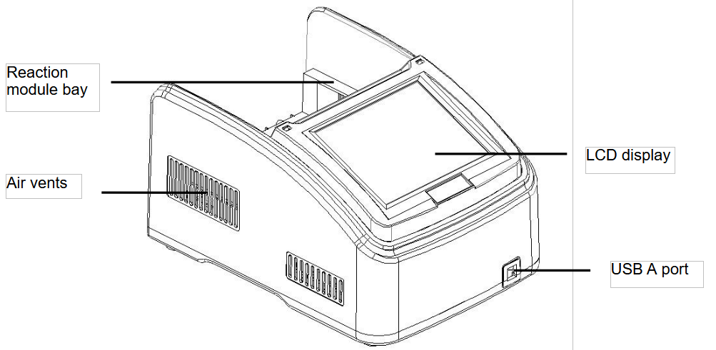
Figure 1
Frontal view of the thermal cycler.
● Reaction module bay - holds inserted reaction module
● Air vents - allows the thermal cycler to cool quickly
● LCD display - displays operating status
● USB A port - connects to a USB key, computer mouse, or other USB devices.
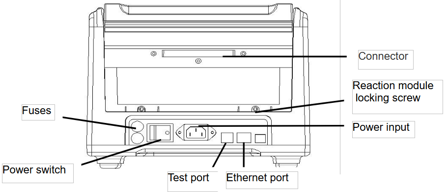
Figure 2
Back view of the thermal cycler.
● Connector - connection between host machine and reaction module
● Reaction module locking screw - locks reaction module
● Test port - for service testing only
● Ethernet port - connects the thermal cycler to a computer
B. Reaction module
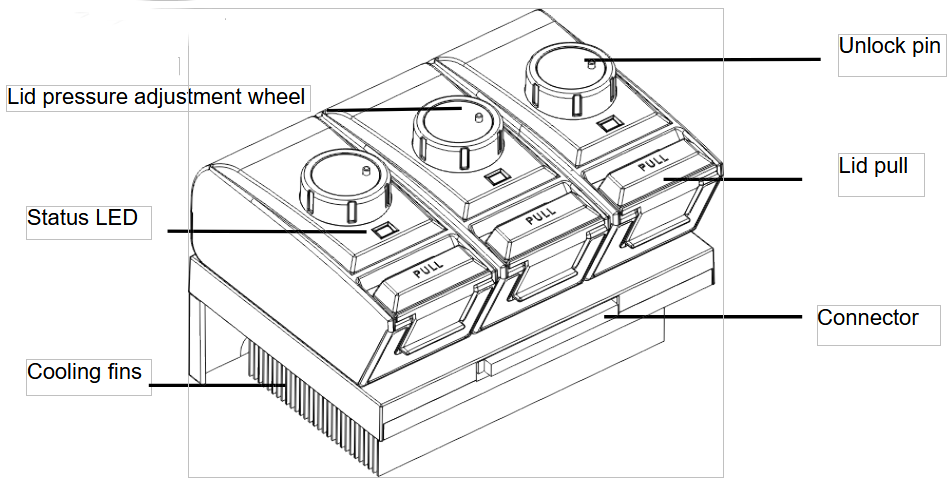
Figure 3
The lid and cooling fins of reaction module.
● Lid pressure adjustment wheel - adjust the lid pressure
● Unlock pin - to unlock wheel
● Status LED - indicates status of reaction module
● Lid pull - opens and closes the lid
● Connector - connection between host machine and reaction module
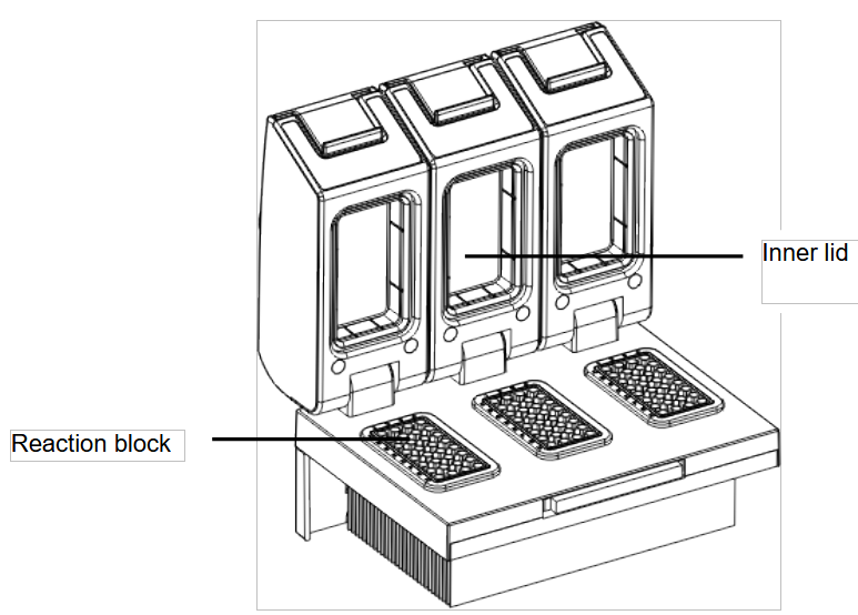
Figure 4
Opening view of reaction module.
●Inner lid - maintains the lid temperature to prevent condensation and evaporation
● Reaction block - holds reaction vessels, including tubes and microplates
C. High Performance Smart Lid
To achieve optimum pressure on the tubes the instrument is equipped with a height adjustable heated lid.
Close the lid:
After the samples have been placed in the block close the lid. Turn the wheel clockwise until you hear a clicking noise. In this mode the pressure will not increase further, even when you keep on turning the wheel.
Note: The pressure of the lid has been optimized for a fully loaded block. If only very few
Tubes are loaded to the block you should place dummy tubes in the four corner positions to avoid damage of tubes by excessive pressure.
Open the lid:
First: Release pressure by turning the wheel counter clockwise. As soon as there is no more
resistance the pressure has been released.
Then: Open the lid with by pushing the front button.
Important: The lid should not be opened under pressure because this leads to damage of the locking mechanism.
D. Releasing blocked lid wheel
Note: When the lid is in the very up or down position, it may happen that the wheel is
uncoupled. In this situation the clutch mechanism is active in both directions (clicking noise in
either direction).
To unlock wheel, press down metal pin with a ball pen and turn wheel carefully. This pin
overrides the automatic clutch mechanism. Thus, care must be taken not to apply excessive
Pressure.
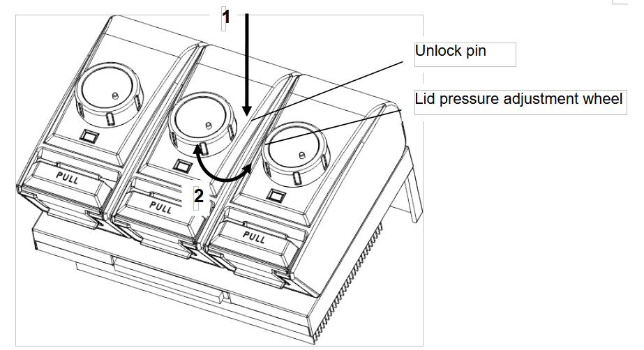
Figure 5
Release lid in upper position:
1) Press pin
2) Carefully turn wheel while holding the pin down CLOCKWISE, until you feel normal resistance (no more clicking noise, clutch is released). Release pin and turn lid down, until
the clutch mechanism is activated (clicking noise, optimum pressure applied).
Release lid in down position:
1) Press pin
2) Carefully turn wheel while holding the pin down COUNTERCLOCKWISE, until you feel
normal resistance (no more clicking noise, clutch is released). Release pin and turn wheel counter clockwise until pressure is completely released. Open lid.
Important: When the clutch mechanism is active (= optimum pressure is applied), do not use pin to further increase lid pressure. This would lead to damage of tubes and instrument !
3.2 Speciality
1. 6 long service life Peltier heating units and form 3 circuits to control 3 temperature zones.2. Reinforced aluminum module with anodizing technology can keep rapid heating-conducting property and have enough corrosion resistance.
3. High heating and cooling rate, max. Ramping rate 5 ℃/s, can save your precious time;
4. 3 blocks independently controlled and can run 3 different PCR programs simultaneously.
5. Stepless adjustable hot lid with pressure-protection, fit tubes of different heights to avoid tube melt and evaporation.
6. Android system, 8” (800×600, 16 colors) TFT color touch-screen with graphical display provides easy use for setting up and monitoring.
7. Built-in multiple standard program file template, can quickly edit the required files.
8. Folder management, user can build directory.
9. The running program and left time can be displayed in real time , allow to edit file when program is running.
10. One-click quick incubation function can meet experiment’s needs such as denaturation, enzyme cutting/enzyme-link and ELISA.
11. Internal flash memory for 10000 typical PCR files in free configurable folders.
12. Hot lid temperature and hot lid work mode can be set to meet different experiment’s need.
13. Automatic restart after power failure. When power is restored it can continue to run unfinished program.
14. GLP report records every step to provide accurate data support for experiment result analysis.
15. User Login Management, three-tier permission, password protection function to ensure data security.
16. Compatible with devices such as Mouse and Keyboard and capable to transfer data and perform software updates via USB Drive,and support USB flash disk to update software.
17. Built in WiFi module, one machine can control multiple PCR instruments at the same time through mobile app or PC software.
18. Support email-alert function when experiment is over.
3.3 Performance
| Model | BTHC-110 |
| Capacity | 3×32×0.2ml |
| Reaction Volume | 5-120μl |
| Temperature Range | 0-105℃ |
| Max. Heating Rate | 5℃/s |
| Max. Cooling Rate | 4℃/s |
| Uniformity | ≤±0.2℃ |
| Accuracy | ≤±0.1℃ |
| Display Resolution | 0.1℃ |
| Temperature Control | Block/Tube |
| Ramping Rate Adjustable | 0.01-5℃ |
| Gradient Temp. Range | 30-105℃ |
| Gradient Spread | 0.1-30℃ |
| Hot Lid Temperature | 30-115℃ |
| Hot Lid Height Adjustable | Stepless Adjustable |
| Number of Programs | 10000 +(USB FLASH) |
| Max. No. of Step | 30 |
| Max. No. of Cycle | 200 |
| Time Increment/Decrement | 1 Sec - 600 Sec |
| Temp. Increment/Decrement | 0.1-10.0℃ |
| Pause Function | Yes |
| Auto Data Protection | Yes |
| Hold at 4℃ | Forever |
| Mobile app | Android |
| WIFI/LAN to computer | Yes |
| LCD | 8inch, 800×600 Pixels, TFT |
| Communication | USB2.0, LAN, WIFI |
| Dimensions | 390mm×270mm×255mm (L×W×H) |
| Weight | 9kg |
| Power Supply | 100-240VAC , 50/60Hz , 600 W |
Table 3
4. Operation Instruction
4.1 Power on
Connect power cord to the back of instrument then plug into power source and switch to "-". . When the instrument is on, the buzzer should be heard and the LCD screen lights up to show the Boot screen . After that, the operating system starts up and then goes to the Self-Test screen (Figure6). During this phase, the LCD screen displays the product name, and its name. When it’s over, the system performs the Home screen as shown below.
Figure 6
The boot screen.

Figure 7
The self-test screen.

Figure 8
The home screen.
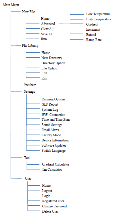
4.2 Menu Structure
4.3 File Instructions
File is composed by Temperature Step and Cycle Step. Each File can hold up to 30 Steps, Temperature Step contains Temperature, Time, Gradient, Ramp Rate, Temperature Increment and Time Extend.4.3.1 Create or Edit File
1). Change Target Temperature and Hold Time• From a new file
Touch “New File” button in the Home screen to create new file.
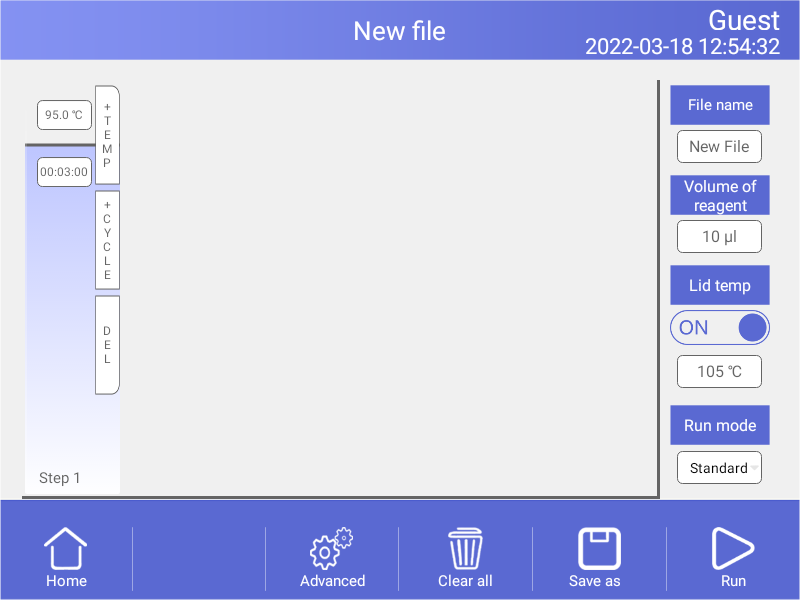
Figure 9
Create a new file
In the New File screen, touch “+Temp” button to add a Temperature Step, touch
“+Cycle” button to add Cycle Step (GOTO step), use the pop-up numeric keypad to
enter a new value for the target temperature or hold time.
From an existing file
In the Home screen (Figure 8), touch “File Library” button to enter File Library
screen (Fig. 10),then Select a file in the File Library screen (Fig. 10), touch “Edit”
button to enter Edit File screen (Fig. 11).
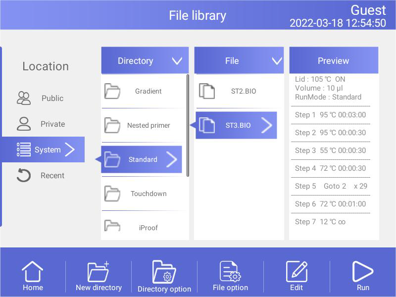
Figure 10
File Library
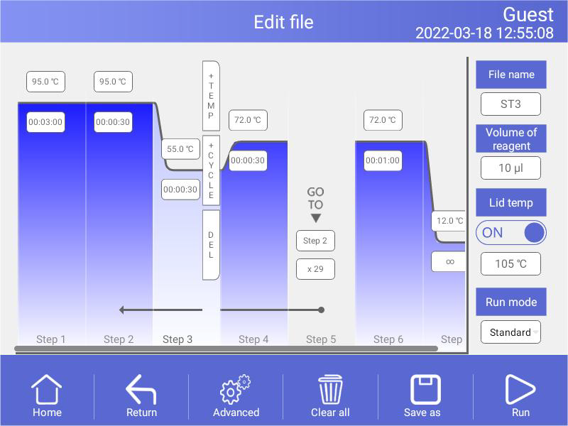
Figure 11
Edit an old file
In the Edit File screen (Fig. 10), select a desired step by touching anywhere in the step. Change a time or temperature by touching the desired field and entering a value using the pop-up numeric keypad. To enter an infinite hold, fill time field with 00:00:00.
2). Run Mode
There are two Run modes: standard mode and fast mode. Users can choose the mode according to their actual needs. The fast mode takes less experimental time than the standard mode.
3). Edit Step
Select a desired step, touch “Advanced” button to enter Advanced screen (Figure 12).
Parameters can be edited by selecting among Gradient, Ramp Rate, Temperature Increment or Time Extend. Table 1 lists the parameters for temperature and gradient steps with the limits of those parameters.
After entering Gradient values the gradient distribution table (Fig. 12) will be shown at bottom of the screen. Touch “OK” to save changes and return Edit File screen (Fig. 11).
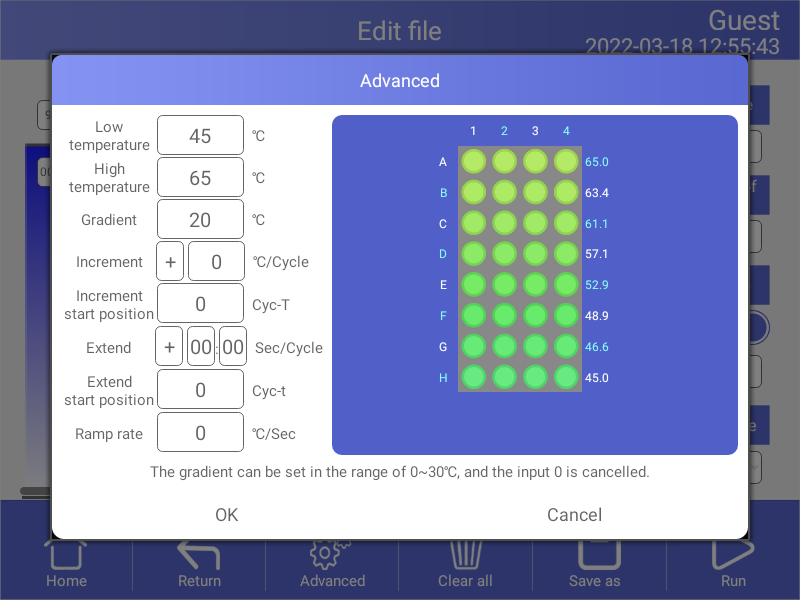
Figure 12
Set the Horizontal Gradient
List of parameters for temperature and gradient steps
| Parameter | Ranges | Description |
| Lower temperature | Temperature in ℃: The target temperature between 0.0 and 105.0℃ in tenths of a degree | Instructs the thermal cycler to ramp to the target temperature. |
| Hold time: The hold tine between 1 sec and 18 hour in the format of hour : min : sec. To enter an infinite hold, touch 0 button, the symbol ∞ (infinite) will come out. | ||
| High temperature | The high temperature in the gradient. The max. temperature is 105.0℃. Enter a temperature within 30.0℃ of the lower temperature. | Instructs the thermal cycler to ramp to the target temperature gradient across the block and hold that temperature gradient for the specified amount of time. |
| Hold time: The hold tine between 1 sec and 18 hour in the format of hour : min : sec. To enter an infinite hold, touch 0 button, the symbol ∞ (infinite) will come out. | ||
| Gradient | The horizontal gradient temperature range between 0.0 and 30℃, the vertical gradient temperature range between 0.0 and 30℃. | The gradient temperature range |
| Increment | A temperature from -10.0℃ to 10.0℃per cycle in tenths of a degree. | Applies only to a temperature step. Instructs the thermal cycler to increment (change) the target temperature of a step with each cycle, where a positive number increases the temperature and a negative number decreases the temperature. |
| Extend | A time from -600 sec to 600 sec per cycle. | Applies to both temperature and gradient steps. Instructs the thermal cycler to extend the hold time with each cycle. A positive number increases the hold time and a negative number decreases the hold time. |
| Ramp rate | A number from 0.1 to 5℃ per sec | Applies only to a temperature step. Instructs the thermal cycler to ramp to the target temperature at the specified ramp rate in that step. |
Table 4
4). Insert A Step
Insert a step if a new temperature, Cycle (GOTO), or gradient step is needed. Follow these instructions to insert a step to the right of a preexisting step.
I. Touch a step to the left where the new step will be inserted.
II. Touch the “+Temp” button to insert a step or the “+Cycle” button to insert a Cycle (GOTO)
III. Touch the time or temperature field to edit the parameter in the new step, or touch the step or times field to edit the parameter in the new Cycle (GOTO).
5). Delete A Step
To permanently remove a step from file.
I. Select the step to be deleted.
II. Touch “Delete” button to delete the selected step.
6). Save File
In the Edit File screen , select the file name edit box, input volume of reagent , lid temperature, as shown in Fig.13, input the "Save as" button after completion, select the save path as shown in Fig.14, or click the "Run" button to run the file directly.
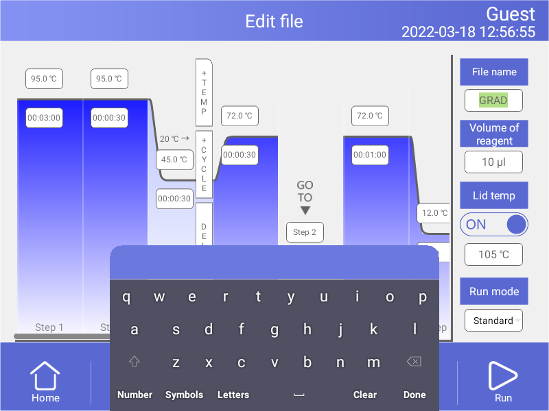
Figure 13
Name file
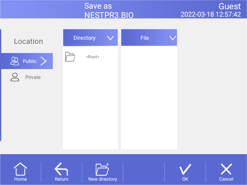
Figure 14
Select path
4.3.2 Delete File
In the File Library screen (Fig.10), touch File Option button to select the file to delete, and the query dialog will pop up when touching“Delete file” button, and delete this file by touching OK(Fig.15). Only one delete per time is allowed to prevent any files being mistakenly deleted.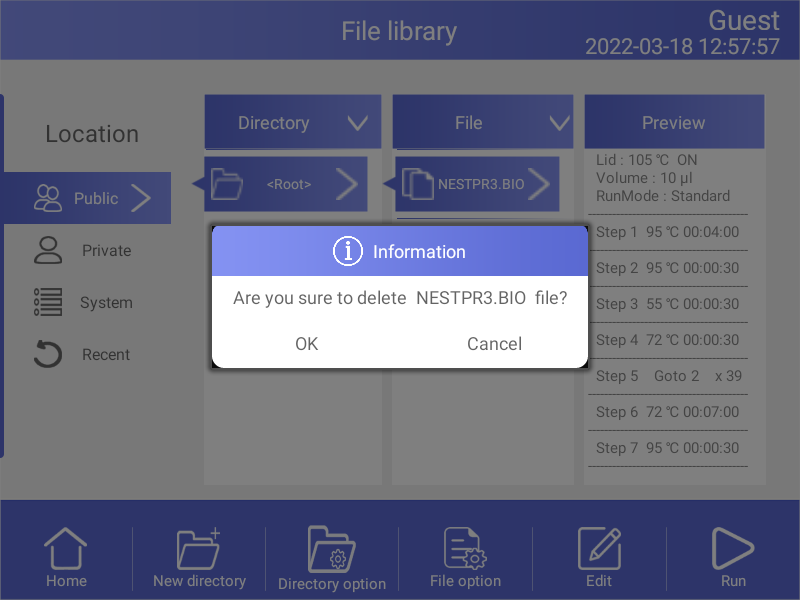
Figure 15
4.3.3 Copy File
In the File Library screen (Fig.10), touch File Option button to select the file to copy and touch Copy file button. Then enter the save path and touch Paste file button to finish copy.4.3.4 Rename File
In the File Library screen (Fig.10), touch File Option button and select the file to rename. Then touch Rename file button and enter new file name in the dialog window to rename files.4.3.5 Run File
In the File Library screen (Fig.10), select the file needed and touch Run button or touch the "Run" button on the new file/edit file screen to pop up the prompt dialog box.Then press the "OK" button to enter the running file screen (Fig.16). In the running file screen (Fig.16) can press the "Edit" button to enter the Edit the running file screen.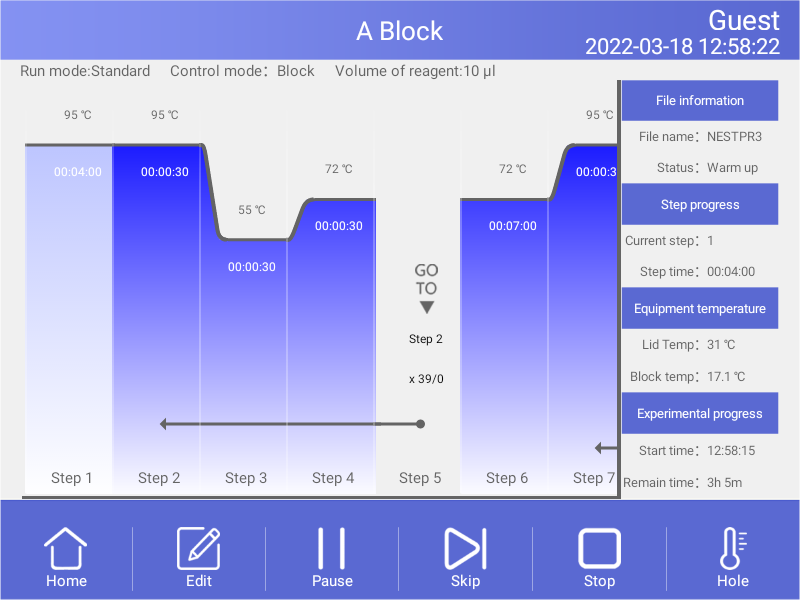
Figure 16
File running.
1). Parameter
● Start Time - system time when file starts to run.
● Remain Time - remaining time for the experiment.
● Lid Temp - current hot lid temperature.
● Step - current step.
● Step Time - current step time.
● Block Temp - current block temperature.
2). Pause
Touch “Pause” button to pause running file and touch “Resume” button to restore running.
3). Stop
Touch “Stop” button to stop a running file.
4). Skip
Touch” Skip” button to jump to next step.
5) . Go to other screen
6). Edit
Touch "Edit" button to enter the Edit the running file screen.
Touch Home button to back the Home screen, or touch Circle in the middle of the screen(Fig.17) to enter the running file screen (Fig.16).
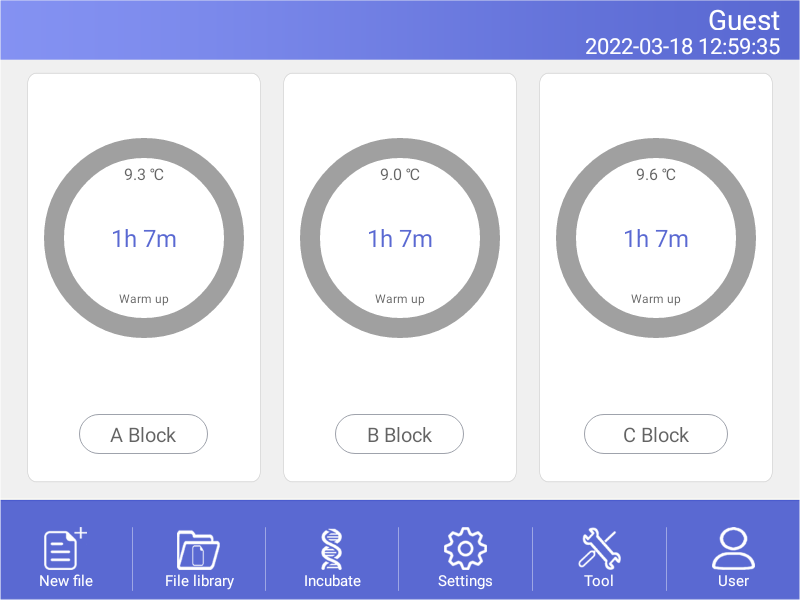
Figure 17
The file is running of home screen.
4.4 Setting
In the Home screen, touch Setting button to enter the Setting screen (Figure18).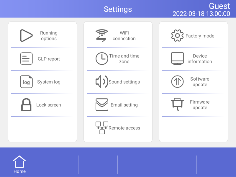
Figure 18
Setting menu
4.4.1 Run Setting
In the Setting screen (Fig.18), select the Run Setting to enter the Run Setting screen (Fig.19).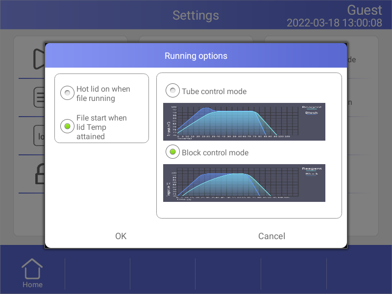
Figure 19
Run parameter setting.
1). Hot lid work mode setting
In total there are 2 working modes and default mode is that the hot lid will be on when file running.
2). LED lights setting
In total there are 2 LED lights work modes and default mode is LED lights turn on circularly when file is running.
3). Temperature control mode
The temperature control mode contains block control mode and tube control mode. The block control mode is suitable for performing normal PCR and the tube control mode is for experiments that require higher environment conditions. the system default is block control mode.
4.4.2 System Setting
In the Setting screen, can set time and date,sound,WiFi connection.1). Time and date
Set the system time and date.
2). Sound
● Keyboard sound - sound when touch button.
● Alarm sound - sound when system error occurs.
● File end sound - sound when file running is complete..
● Temp to reach sound - sound when the target temperature reaches.
3).WiFi connection
If you need to open WiFi function, touch "Open WiFi" button.
4.4.3 E-mail Setting
In the Setting screen , select E-mail alerts to enter the E-mail Setting screen.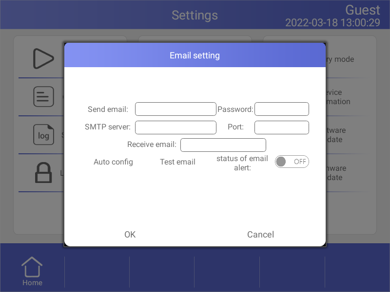
Figure 20
E-mail setting.
1) . Status of email alert
After program is over it will automatically send email if chose Enable.
2) . Test email
Test email function is to test whether email can send or not.
3) . Save
Touch “OK” to save information and email setting record.
4.4.4 GLP Report
Record of every file name, time of start run this file, block number, source files path (Figure21).● GLP Report - Record the time and temperature for each step.
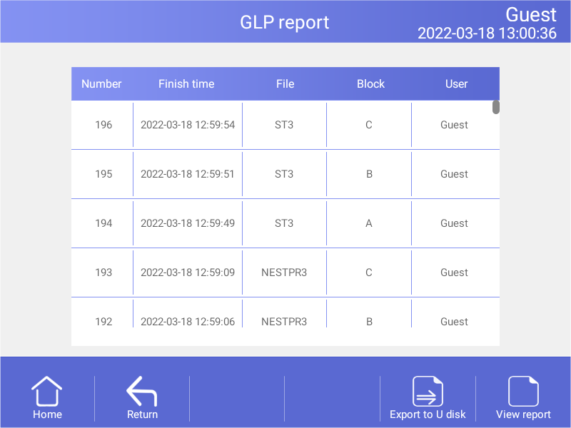
Figure 21
GLP Report.
4.4.5 Device Information
Show the machine name, the SN., the control version and UI version (Figure22).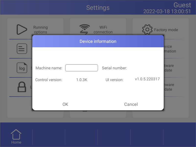
Figure 22
Local information.
4.4.6 Software Update
Copy the new software to the root directory; insert the USB flash disk into the USB port, thentouch “Software update”, return to Android desktop when updating, and immediately reopen the updated App .
4.5 Tool
In the Home screen, touch Tool button to enter the Tool screen (Figure23).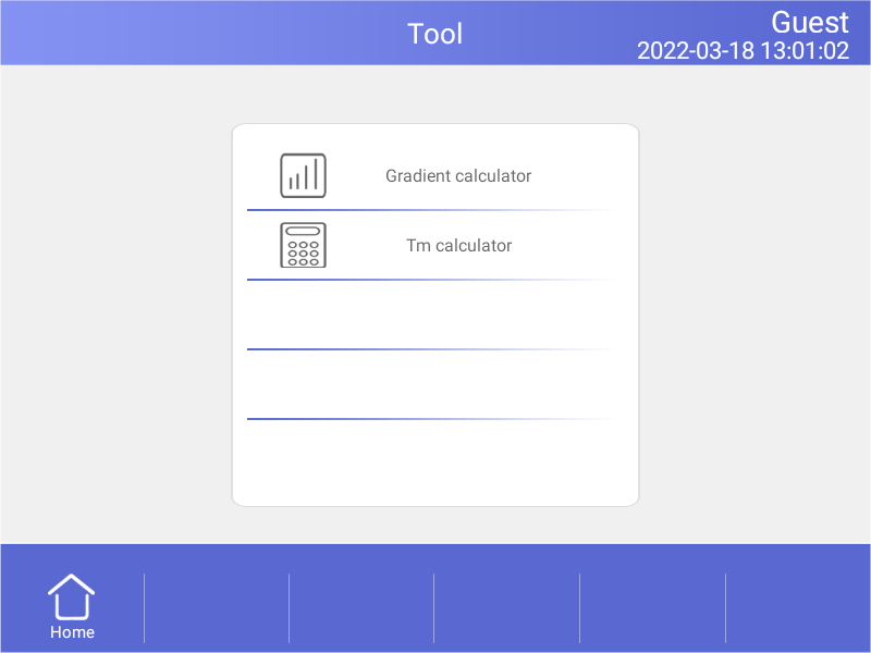
Figure 23
Tool menu.
4.5.1 Gradient Calculator
The temperature value for each column is shown after entering the block target temperature and gradient range.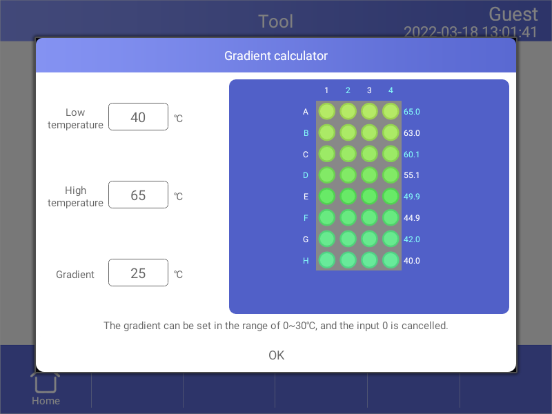
Figure 24
Gradient calculator.
4.5.2 Tm Calculator
Touch the fields to enter concentrations and the primer sequences,then touch Calculate Tm to calculate the melting temperatures,Maximum input for each primer sequence is 30 .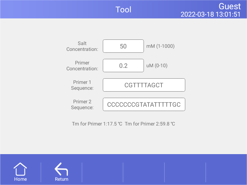
Figure 25
Tm Calculator.
4.6 Incubate
In the Home screen, touch Incubate button to enter the Incubate wizard screen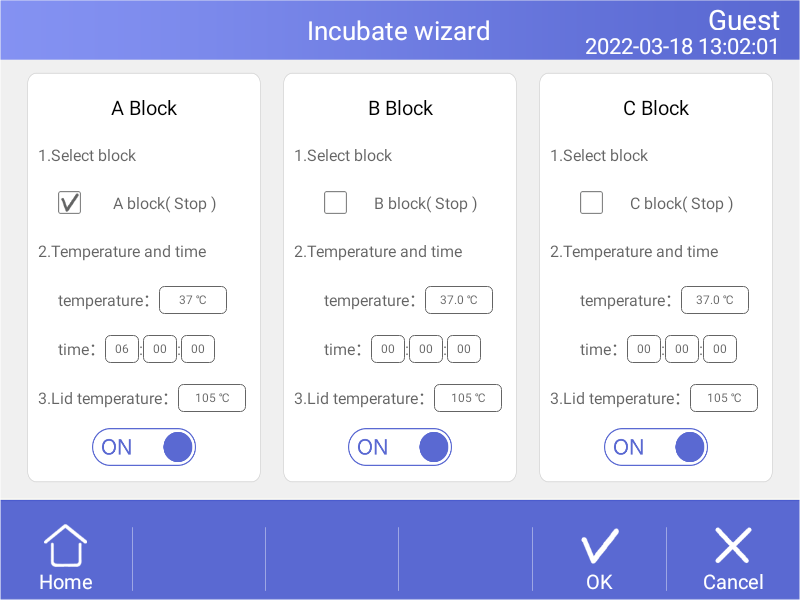
Figure 26
Incubate wizard.
In the Incubate wizard screen , select the desired block and enter the block temperature and the hold time. Then touch Start button to enter Incubate Running screen.
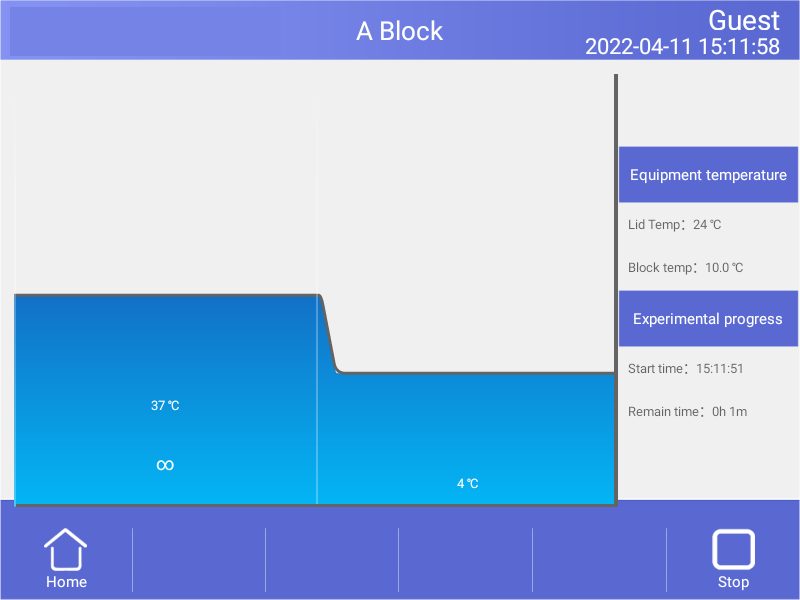
Figure 27
Incubate running.
4.7 Log In
In the Home screen, touch User button to enter the User screen (Fig.27).NOTE: Administrator user's password is “123456”, you can change the password after logged in.
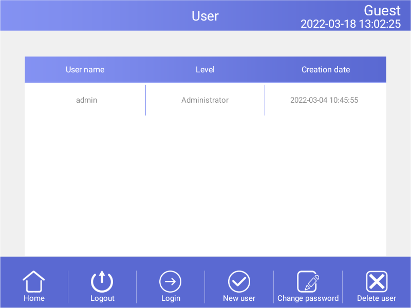
Figure 28
User management.
4.7.1 New User
In the User screen , touch New user button to enter the New User screen .Enter user name and password, then touch OK button to enter the User screen. In the User screen, select the Registered user who needs to log in and press the "Login" button.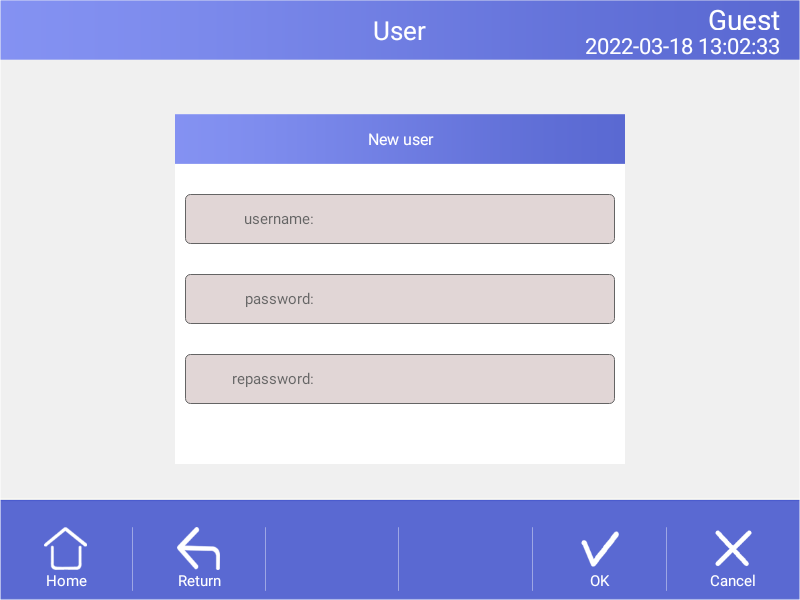
Figure 29
New user.
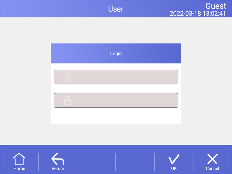
Figure 30
Login
4.7.2 Change Password and Delete User
Only after login can passwords be changed and users be deleted, can other users be deleted from the login administrator account.5. Maintenance and Troubleshooting
5.1 Machine Maintenance
1). Regular cleaningA. Clean the holes on reaction block with neutral soap solution (Do not use any solvent containing strong alkali, strong alcohol and organic solution).
B. Spaces near the left, right air vents and under the machine should be always kept free. It is very important to clean the dust around air vents regularly.
C. Clean the reaction block regularly and remove any residue inside cavities to prevent any affects to the temperature control. (we suggest to use soft cloth).
2).Replace fuse
The machine has two fuses. Replace it according to the following once damage occurs.
A. Turn off the machine and unplug power source.
B. Unscrew the fuse box with flat screwdriver and replace the damaged fuses with new 8A 250V fuses. After replacement, screw back in the fuses box.
Note: Please contact your supplier for repair when encountering any problem replacing fuses.
5.2 Troubleshooting
1).Dissatisfactory ResultsBiological, programmatic and hardware problems may contribute to any unsatisfied results of experiment. In order to distinguish the hardware problems from other possible problems, the machine is equipped with built-in self-test hardware and self-diagnosis software. Below is the detailed description. According to the experiences, most problems are related to biological and programmatic factors.
FAQ as follows:
A. Incorrect or insufficient reactants.
B. Denaturation temperature is too high or too low. It is suggested to set the temp. within range of 90-95℃ for 40 seconds. The duration can be adjusted in accordance with reaction volume.
C. Annealing temp. is too high or too low; It should be between 55-70° C and 20 to 30 chains.
D. Reactant concentration is too high or too low.
E. Preparation process without special treatment.
F. Time and temperature value in progress are not appropriate.
G. The temperature of sample is slightly too low while the temp. of block is slightly too high.
H. Check whether the PCR tubes are well placed. Smearing little mineral oil on the surface of holes will increase the thermal conductivity.
2). Machine’s self-test and self-diagnosis function
The machine will run the self-test program when booting. The software and hardware of machine will show the results so as to inform users the potential problems, minimize the failure of experiment and display the error message when problem occurs.
5.3 Notes
1). PowerA. No special requirement for power supply. Any AC power source within range of 100-240V is applicable. However, to prevent from causing any damage to the machine, it is better to apply low voltage fluctuation power sources, Otherwise consider to install power supply regulator.
B. It’s prohibited to cut off the power to terminate a running experiment. It’s very harmful to the machine.
2).LCD screen
Avoid using UV disinfection to clean the machine to prevent any damage.
Avoid any bump or scratch to the LCD screen while using.
3). Note about cleaning
Avoid any liquid getting inside the machine while cleaning the base of machine. Due to the possible usage of radioactive substance during experiment, please carefully handle cleaning.. It is not suitable to use the machine in moisture or hot environment.
Note: Please do read the notes carefully! you may damage the machine if don’t operate according to the above requirements.
5.4 Error Messages and Correspond Solutions
| No. | Error message | Cause and correspond solution |
| 1 | File name can not be empty | File name does not support null character |
| 2 | If have same file name, Please re-name | Don’t support multiple files with the same name’s file. |
| 3 | Module sensor 1, short circuit | Hardware problem, need to repair |
| 4 | Module sensor 1, open circuit | Hardware problem, need to repair |
| 5 | Module sensor 2, short circuit | Hardware problem, need to repair |
| 6 | Module sensor 2, open circuit | Hardware problem, need to repair |
| 7 | Module sensor 3, short circuit | Hardware problem, need to repair |
| 8 | Module sensor 3, open circuit | Hardware problem, need to repair |
| 9 | Module sensor 4, short circuit | Hardware problem, need to repair |
| 10 | Module sensor 4, open circuit | Hardware problem, need to repair |
| 11 | Module sensor 5, short circuit | Hardware problem, need to repair |
| 12 | Module sensor5, open circuit | Hardware problem, need to repair |
| 13 | Module sensor6, short circuit | Hardware problem, need to repair |
| 14 | Module sensor 6, open circuit | Hardware problem, need to repair |
| 15 | Radiator sensor short circuit | Hardware problem, need to repair |
| 16 | Radiator sensor open circuit | Hardware problem, need to repair |
| 17 | Lid sensor short circuit | Hardware problem, need to repair |
| 18 | Lid sensor open circuit | Hardware problem, need to repair |
| 19 | Power output short circuit | Hardware problem, need to repair |
| 20 | Module temperature too high | Air flow vent is blocked or circuit problem, need to repair if latter |
| 21 | Module temperature too low | Temperature of environment is too low or circuit problem, need to repair if latter |
| 22 | Radiator temperature too high | Air flow vent is blocked or fan problem, need to repair if latter |
| 23 | Radiator temperature too low | Temperature of environment is too low or circuit problem, need to repair if latter |
| 24 | Lid temperature too high | circuit problem, need to repair |
Table 5
5.5 Cause of The Abnormal Phenomenon And Correspond Solution
| No. | Description of problem | Cause and correspond solution |
| 1 | No any display after opening the machine | Check whether plug inserted correctly and power output has electricity, pull out the plug while turning off ,and check the fuse |
| 2 | Turn on, the machine start running according to the program | The power was off before ending the last program |
| 3 | The fan run fast some time, slow sometimes | Normal. fan is used dissipating heat while pump is working, not for reaching the sited temp. |
| 4 | Have Slight pat or squeaking sound while machine is working | Normal. When need large power for intense or cold, the switch power supply is adjusted automatically causing the sound of pat or squeaking |
| 5 | Increasing or decreasing module temperature too slow | Check whether the setting of rate of variable temperature and fan is normal or not |
| 6 | Wrong display appears in the screen | Caused by electrostatic pulse or power surge. please turn off and open, does not affect program running |
Table 6
Note: If the above problems can’t be solved, please contact the supplier in time.
6. After-sales Service
1. This product is warranted under normal usage to the original purchaser for two years from the date of purchase.2. Lifetime service guarantee. The local dealer, maintenance station and regional offices will provide you excellent after-sales service.
3. The foregoing maintenance free service is only applicable to products sold as new.
Free maintenance, product return and exchange shall not be provided under any one of the following circumstances even in the warranty period:
1). Damage caused by natural disasters factors (such as fire, earthquake, flood, wind disaster, thunderbolt etc.) and failure conditions caused by abnormal voltage, public nuisance and chemical substance.
2). Failure or damage caused by use this product under abominable conditions (such as oil fume, dust, damp and direct sunlight etc.) or inappropriate use according to the instruction book.
3). Damage caused by drop, move, transport, entry of foreign matter and other factors unrelated to manufacture process.